


Quick Research
Generate reliable direction feasibility study reports for your R&D in just a few steps.

Technical Q&A
Discover and master advanced knowledge NOW. Basics, ideas, possibilities, all at once.

Find Solutions
As an expert in R&D theories, this can generate solutions to your technical problems instantly.

Evaluate Feasibility
Analyze your overall solution with one click, know your potential R&D risks in advance.

Monitor Landscape
Get weekly tech updates, stay abreast of the latest tech innovations and key insights.
Hollow pipe
A hollow tube and tube wall technology, applied in the field of hollow tubes, can solve the problems that half parts cannot be folded into sheets, the transportation volume is small, and the occupied space is large.
- Summary
- Abstract
- Description
- Claims
- Application Information
AI Technical Summary
Problems solved by technology
Method used
Image


Examples
Embodiment Construction
[0049] The present invention will be further described below in conjunction with the accompanying drawings and embodiments.
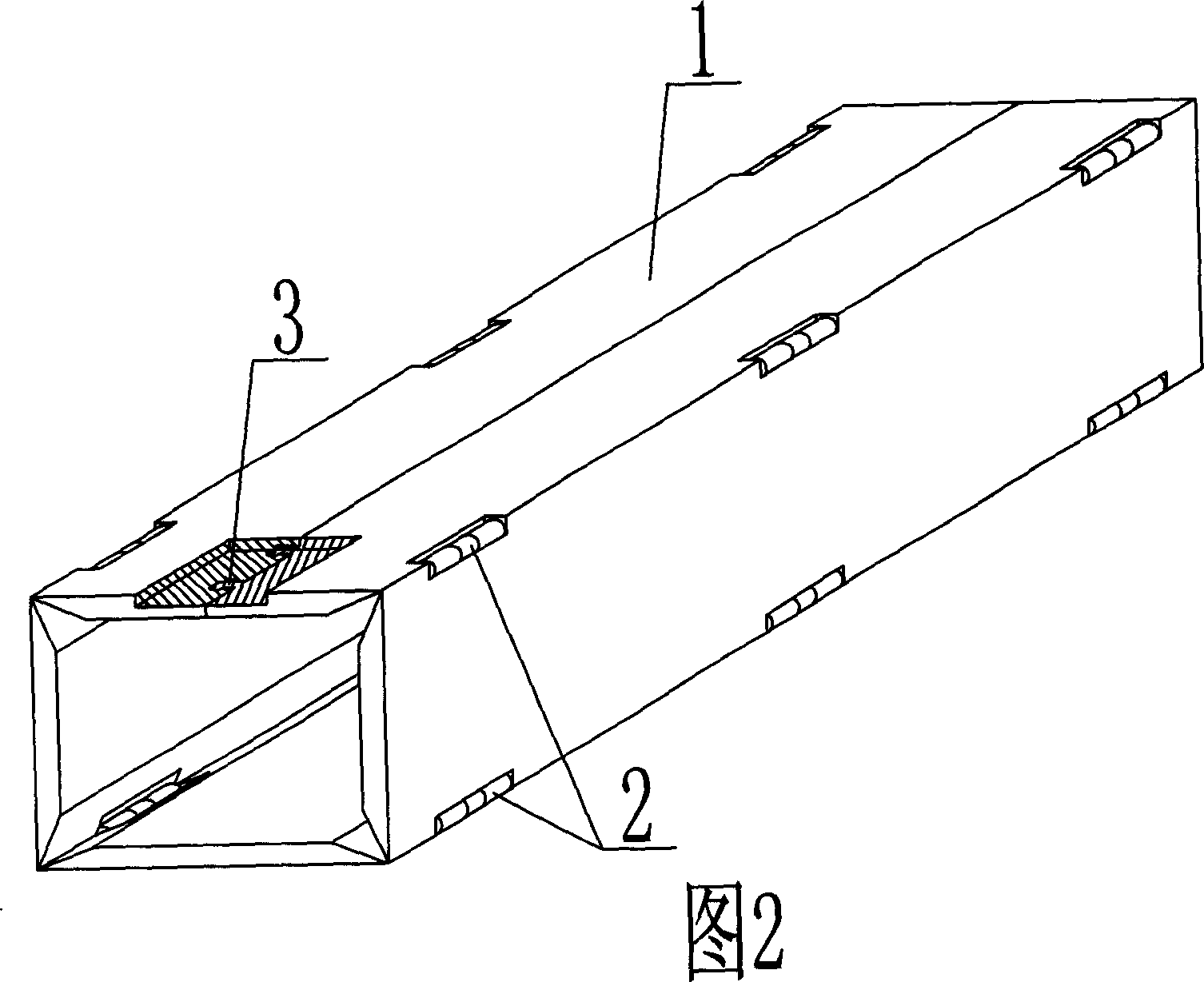
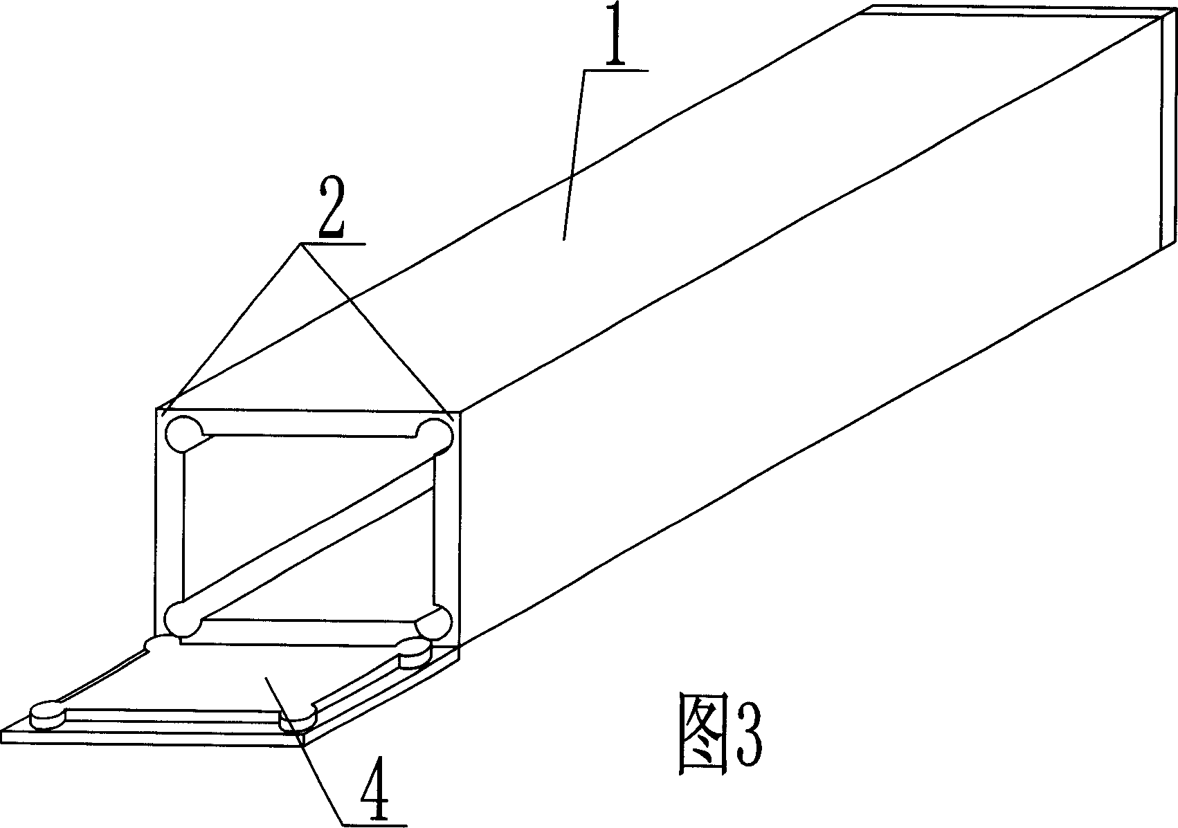
[0050]As shown in the accompanying drawings, the present invention includes an annular pipe wall 1 and a sealing plate 4, and is characterized in that the annular pipe wall 1 is a pipe wall that can be folded into a plate shape, and the longitudinal folding part of the pipe wall is movable. The hinge 2 and the sealing plate 4 are connected to the pipe wall as male and female grooves 5 . In each accompanying drawing, 1 is a tube wall, and 2 is a living hinge. In the following accompanying drawings, those with the same numbering have the same description. As shown in Figure 5, the ring-shaped pipe wall 1 is a pipe wall that can be folded into a sheet shape, the longitudinal folding part of the pipe wall is a living hinge 2, and the sealing plate 4 is connected to the pipe wall as a male and female groove 5. .
[0051] The invention is characterized in t...
PUM
 Abstract
Description
Claims
Application Information
 - R&D Engineer
- R&D Manager
- IP Professional
- Industry Leading Data Capabilities
- Powerful AI technology
- Patent DNA Extraction
Browse by: Latest US Patents, China's latest patents, Technical Efficacy Thesaurus, Application Domain, Technology Topic, Popular Technical Reports.
© 2024 PatSnap. All rights reserved.Legal|Privacy policy|Modern Slavery Act Transparency Statement|Sitemap|About US| Contact US: help@patsnap.com