Self-correcting circuit for mismatch capacity
An automatic correction and circuit technology, applied in the direction of circuits, electrical components, electric solid devices, etc., can solve the problems of large digital circuit hardware implementation area, increased circuit design complexity, and high circuit complexity
- Summary
- Abstract
- Description
- Claims
- Application Information
AI Technical Summary
Problems solved by technology
Method used
Image
Examples
Embodiment Construction
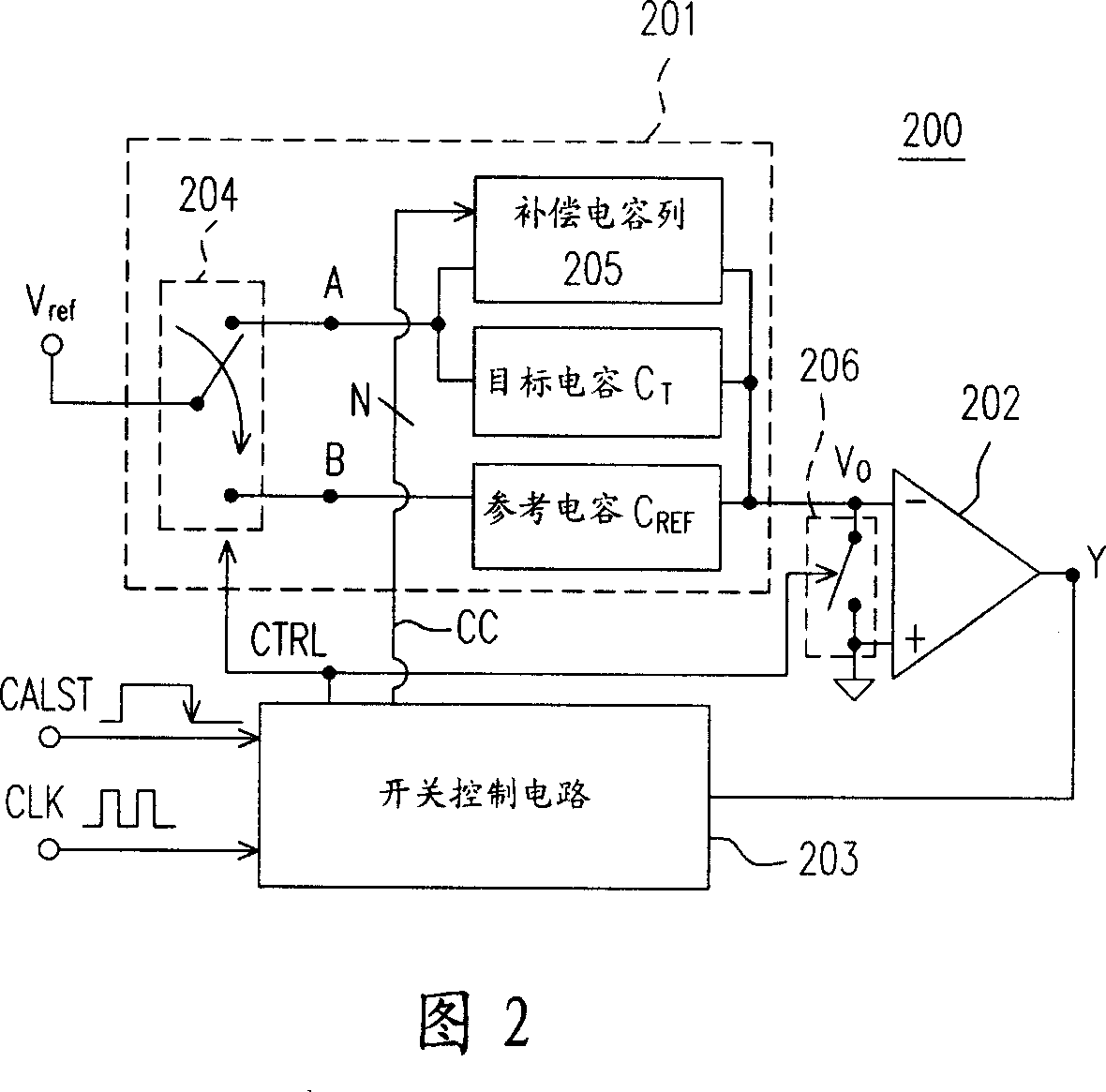
[0058] FIG. 2 is a structural diagram of an automatic correction circuit 200 for capacitance mismatch according to an embodiment of the present invention. The structure of the auto-calibration circuit 200 will be described below first, and then its operation flow will be described in detail.
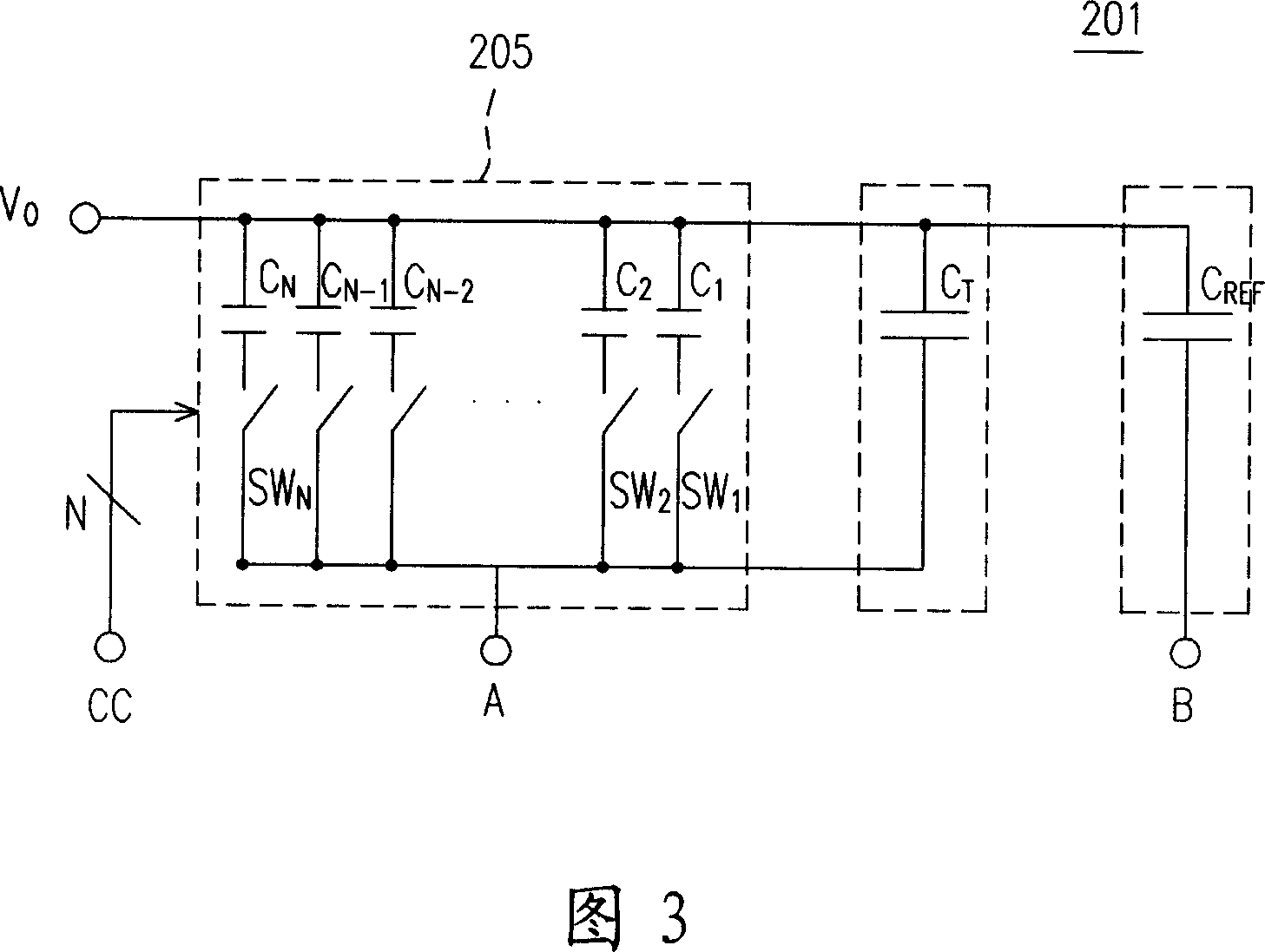
[0059] The automatic calibration circuit 200 mainly includes a sample-and-hold circuit 201 , a comparator 202 , and a switch control circuit 203 . Wherein, the sample hold circuit 201 includes a switch 204, a compensation capacitor column 205, a target capacitor C T , and the reference capacitor C REF, and provide the output voltage Vo.
[0060] The switch 204 is controlled by a switch control signal CTRL. If the switch control signal CTRL is in the first state (logic 1 in this embodiment), the switch 204 conducts the reference voltage Vref and the contact B; if the switch control signal CTRL is in the second state (logic 0 in this embodiment), Then the switch 204 conducts the refere...
PUM
 Abstract
Description
Claims
Application Information
 - R&D
- Intellectual Property
- Life Sciences
- Materials
- Tech Scout
- Unparalleled Data Quality
- Higher Quality Content
- 60% Fewer Hallucinations
Browse by: Latest US Patents, China's latest patents, Technical Efficacy Thesaurus, Application Domain, Technology Topic, Popular Technical Reports.
© 2025 PatSnap. All rights reserved.Legal|Privacy policy|Modern Slavery Act Transparency Statement|Sitemap|About US| Contact US: help@patsnap.com


