
A method and device for relay amplification in TD-SCDMA system

A TD-SCDMA, 1.TD-SCDMA technology, applied in the field of relay amplifier devices, can solve the problems that terminals cannot access the system and cannot increase coverage, etc.

Active Publication Date: 2007-05-16
成都芯通软件有限公司
View PDF0 Cites 8 Cited by
  • Summary
  • Abstract
  • Description
  • Claims
  • Application Information

AI Technical Summary

Problems solved by technology

If the above-mentioned repeater only provides an amplifier and does not participate in the action of the entire transceiver channel controlled by the system, it cannot meet the requirements
Third, the characteristics of TD-SCDMA multi-carrier work also lead to the inability to use the above-mentioned repeater to increase coverage
If only the carrier frequency is changed, the terminals within the coverage area of ​​the repeater will not be able to access the system

Method used


Image

  • A method and device for relay amplification in TD-SCDMA system
  • A method and device for relay amplification in TD-SCDMA system

Examples


Embodiment Construction

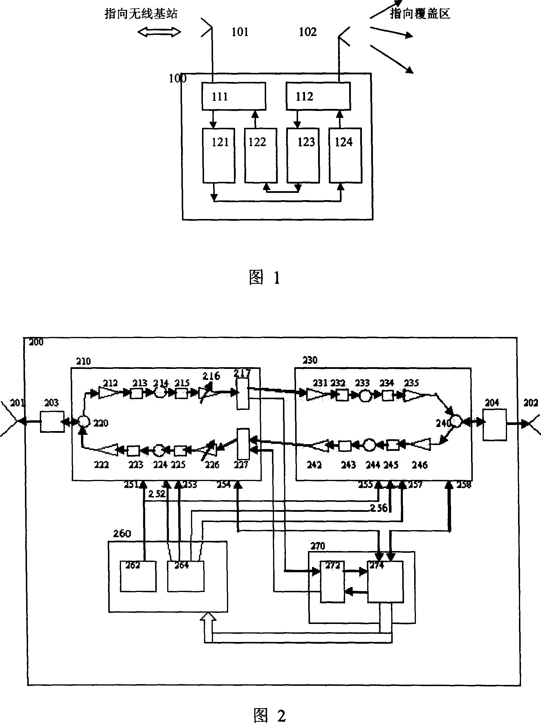
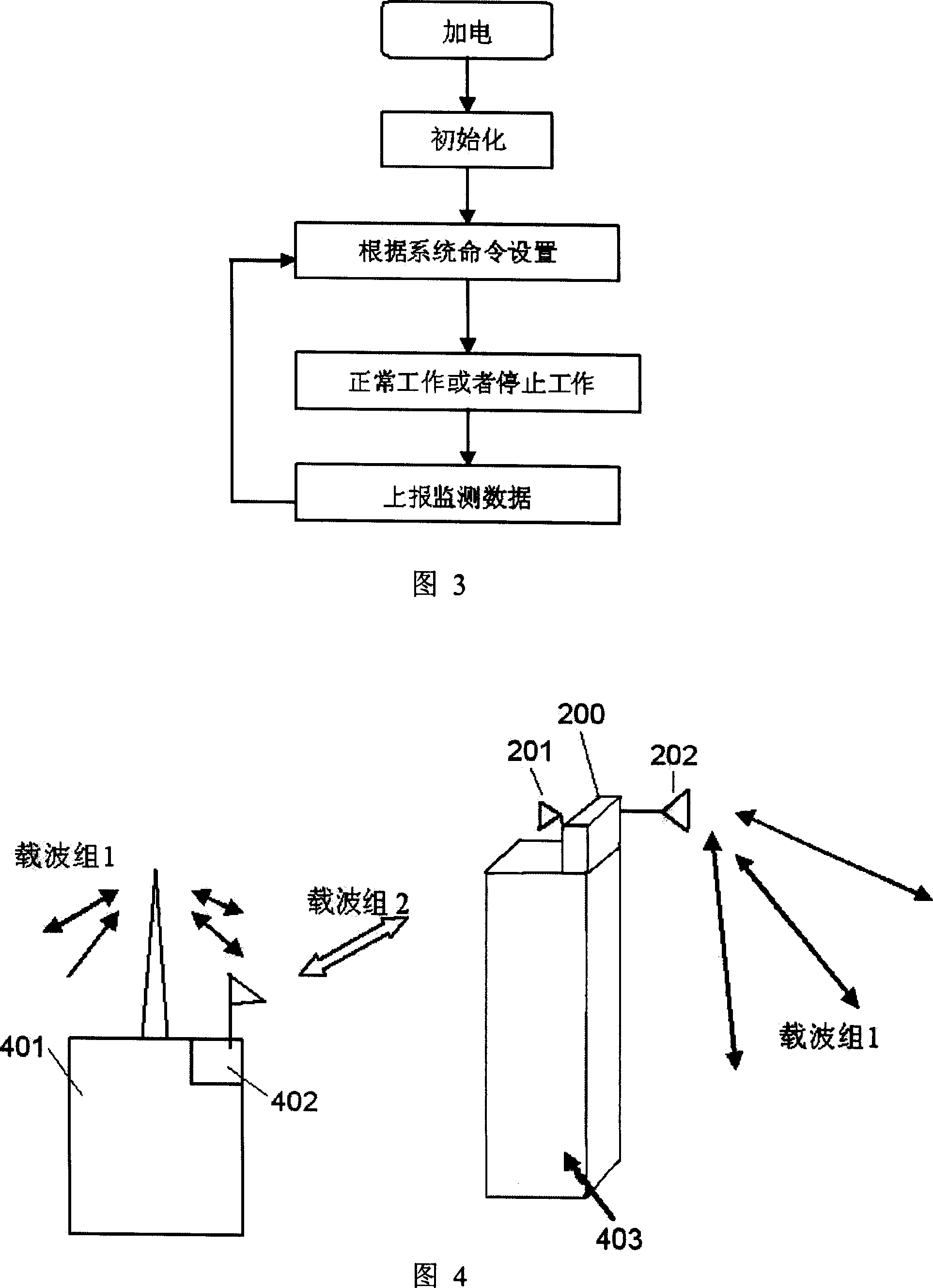
[0021]What Fig. 2 shows is to realize a kind of repeater amplification device of the TD-SCDMA system repeater amplification method between the wireless base station and the user terminal proposed by the present invention, that is, the basic structure of the TD-SCDMA system "Repeater (Repeater)" structure. There are TD-SCDMA radio frequency transceivers connected with two antenna units in this "repeater" 200: the first TD-SCDMA radio frequency connected with the first antenna 201 pointing to the base station and the radio frequency filter 203 connected with it The transceiver 210 and the second TD-SCDMA radio frequency transceiver 230 are connected to the second antenna 202 and the radio frequency filter 204 connected to the coverage provided by it.

[0022] The first TD-SCDMA radio frequency transceiver 210 working on the base station side can be a typical superheterodyne radio frequency transceiver, and its structure can include a low noise amplifier 212, a radio frequency fi...


PUM


Abstract

The related relay amplification device in TD-SCDMA system comprises: a couple of correlative RF transceivers orientated BS and coverage respectively, a frequency and clock structure unit to provide Eigen frequency and timing-enable control for two transceivers and feed back work unit working state to BS, a TD-SCDMA terminal baseband circuit unit to use the BS-orientated transceiver to complete initiation and build communication with BS to get network synchronism time and emission power parameter and computer needed up-down gain for work state monitor.

Description

technical field [0001] The invention relates to a relay amplification device and method of a TD-SCDMA system in the third-generation mobile communication. Background technique [0002] In second-generation mobile communication systems such as GSM and IS-95CDMA, in order to overcome the shielding of radio wave propagation between wireless base stations and user terminals, optimize cell coverage, expand cell coverage, and solve indoor coverage, the so-called " "Repeater", that is, a relay amplification device is set between the wireless base station and the user terminal, and good results have been achieved. Its implementation is shown in Figure 1, which consists of a pair of amplifiers, namely: one amplifier is composed of an antenna 101 pointing to the wireless base station, a duplexer 111, a radio frequency receiver 121 and a radio frequency transmitter 122, and the other amplifier is composed of an antenna 101 pointing to the coverage area. The antenna 102, the duplexer 1...

Claims


Application Information

Patent Timeline
IPC IPC(8): H04B7/14H04Q7/38H04B7/26
Inventor 李睿
Owner 成都芯通软件有限公司
Learn More