
Self-injection underwater perforating twist-sucking drilling machine

A penetrating and twisting suction technology, which is applied in the field of self-penetrating underwater drilling drills, can solve the problem of high cost, achieve the effects of avoiding use, reducing construction costs, and significant economic benefits

Inactive Publication Date: 2007-05-16
NEPTUNE OFFSHORE ENG DEV
View PDF0 Cites 3 Cited by
  • Summary
  • Abstract
  • Description
  • Claims
  • Application Information

AI Technical Summary

Problems solved by technology

[0003] In order to overcome the problem that the traditional underwater drilling equipment depends on the drilling ship and the cost is too high, the present invention proposes a self-penetrating underwater drilling drill

Method used


Image

  • Self-injection underwater perforating twist-sucking drilling machine
  • Self-injection underwater perforating twist-sucking drilling machine

Examples


Embodiment Construction

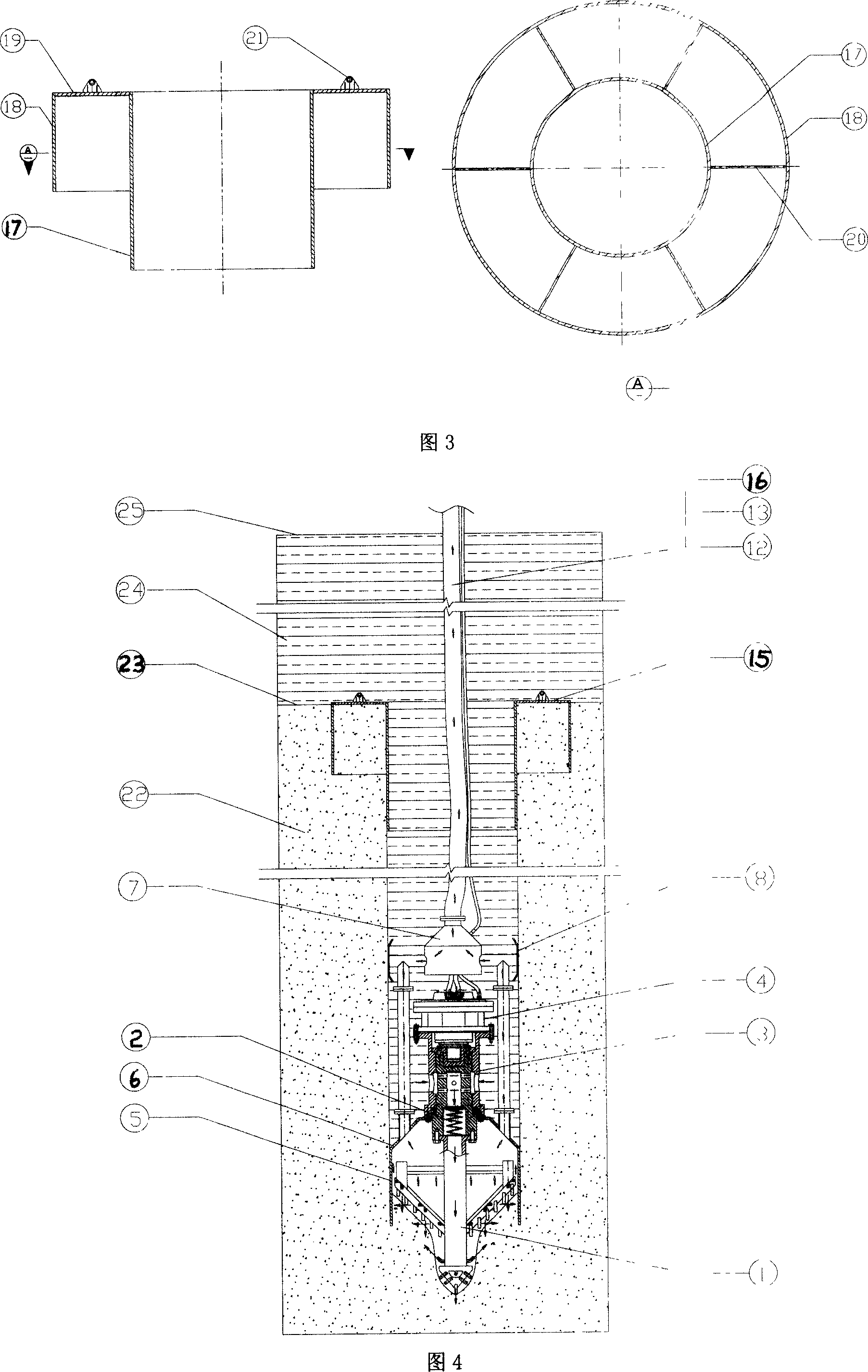
[0013] A self-penetrating underwater drilling cutter suction drilling rig, which is constructed from the following parts from bottom to top (see Figure 1)

[0014] The jet drill (1) includes a center drill and a drill frame: the center drill is hollow tubular, with a cutter plate and drill teeth at the lower end; the triangular structure welded to the drill frame and steel pipes provides sufficient rigidity, and is also a high-pressure water passage. The water nozzle, sprays high-pressure water flow when the drill bit is drilled. A low-pressure shut-off valve (2) is installed on the upper end of the jet drill bit (1), and its upper part is an over-current swivel head (3). Drill bit (1) is connected with flange. The rotating shaft of the over-current swivel head (3) is a hollow structure, with side holes in the middle and the upper end, its function is to transmit the rotational torque of the hydraulic motor (4) to the drill bit, and let the water outside the over-current swiv...


PUM


Abstract

A self penetrating underwater drilling and sucking machine comprises a jet bit (1), a low voltage cut-off valve (2), a overflowing swivel head (3), a hydraulic motor (4), a suction hood(5) (6), a pneumatic lift pump (7), a sliding sleigh (8), a slurry output hose (12), a hydraulic pipe (13) and a high pressure air pipe (16). The overflowing rotating head (3) that is short and consistent in length will be replaced by the traditional drill rod string that extends when it drills deeper and deeper. Self-penetration of the drill can be realized relying on the pressure gap inside and outside caused in the slurry releasing process by the sucking hood conical surface. A slurry releasing hose (12) connected to the pneumatic lifting pump on the driller, leads to the operating boat on the water. The waterborne operating boat controls the driller through a hydraulic pipe (13) and a high pressure air pipe. The perpendicularity of the drilling hole and stability of the aperture are ensured of with the sliding sleigh (8) and the protective wall structure (15) respectively. The inventions excels itself with its small size and light weight of the driller, feasibility of operating on the sea, effective in cost reduction and it successfully avoids the traditional driller's dependency on some big scale drilling ship.

Description

Technical field [0001] The invention belongs to the innovation of an underwater drilling tool. Background technique [0002] The traditional underwater drilling machine is an underwater drilling rig, which consists of a drill bit, a drill pipe, a turntable and an electric motor from bottom to top. The electric motor and the turntable are placed on the drill floor above the water surface; the drill pipe and the drill bit connected with the turntable extend into the underwater drilling hole. When performing underwater drilling, the electric motor is turned on to drive the turntable to rotate, and the torque is applied to the drill pipe and transmitted to the drill bit. The drill pipe is a hollow steel pipe, through which the mud is passed through to the outlet of the drill bit, and returns to the surface of the water from the outside of the drill pipe along the hole wall to form a circulation system. The hollow drill pipe is lengthened in sections with the deepening of the d...

Claims


Application Information

Patent Timeline
Patent Type & Authority Applications(China)
IPC IPC(8): E21B7/18E21B10/60
Inventor 王翎羽
Owner NEPTUNE OFFSHORE ENG DEV
Learn More