Mould control apparatus for powder molding press
A technology for control devices and molding machines, applied in the direction of presses, material forming presses, manufacturing tools, etc., can solve problems such as high machine costs, difficult maintenance, and complex mold ejection mechanisms, and achieve high production efficiency and stable work sex high effect
- Summary
- Abstract
- Description
- Claims
- Application Information
AI Technical Summary
Benefits of technology
Problems solved by technology
Method used
Image
Examples
Embodiment 1
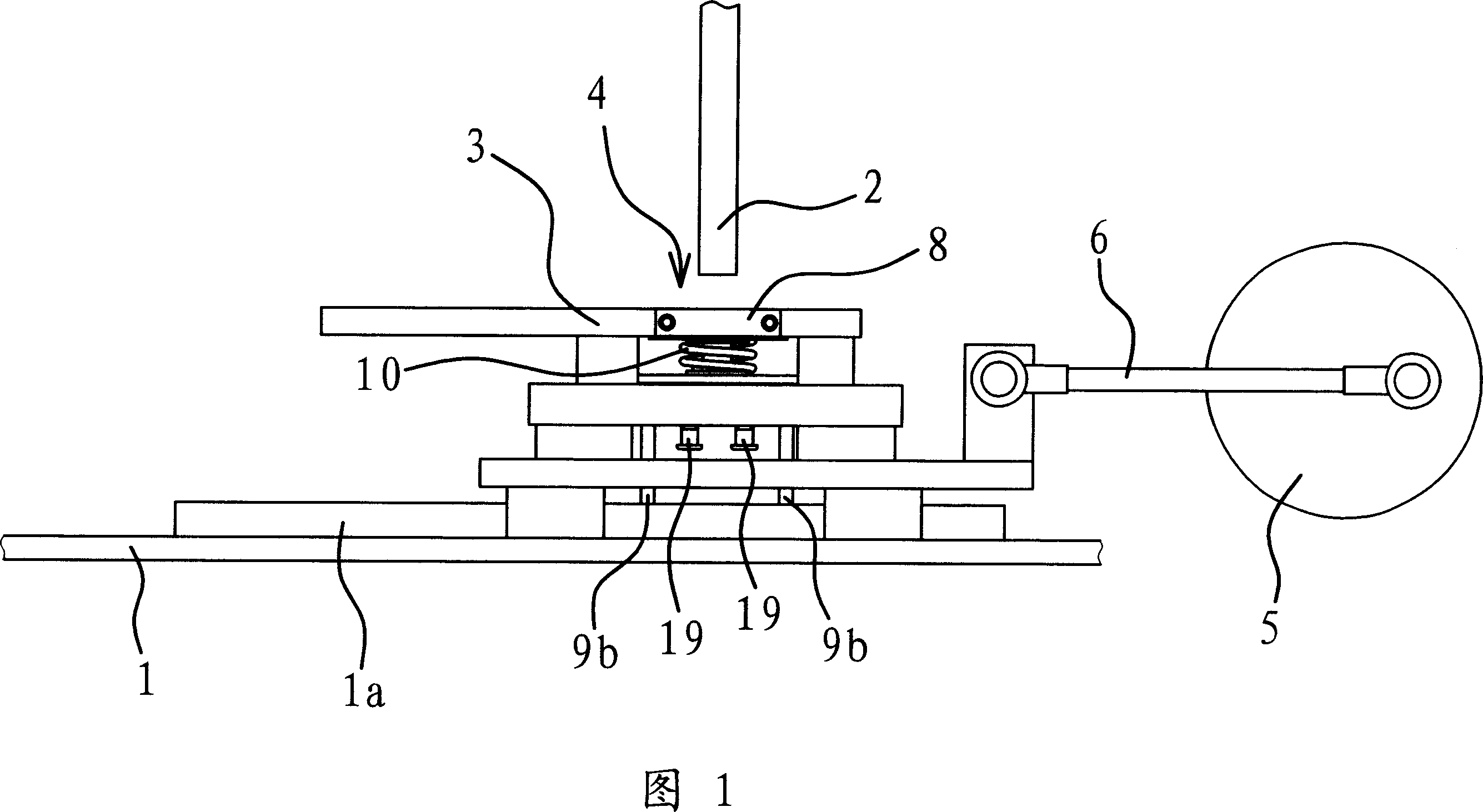
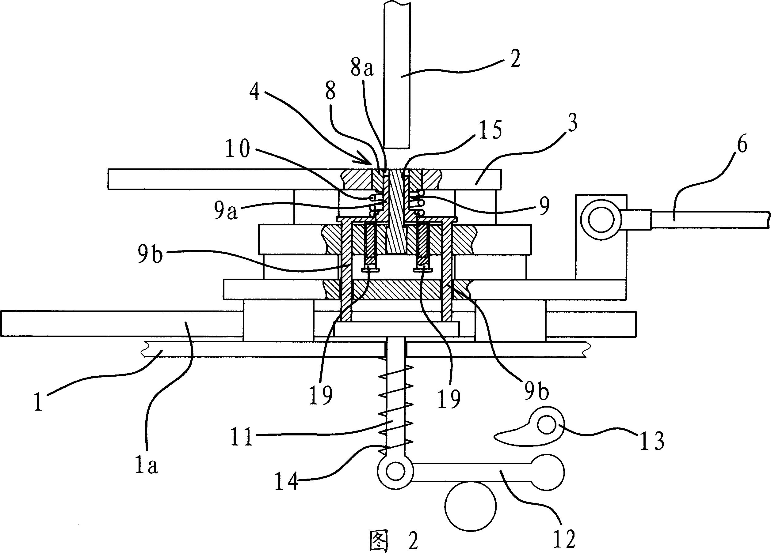
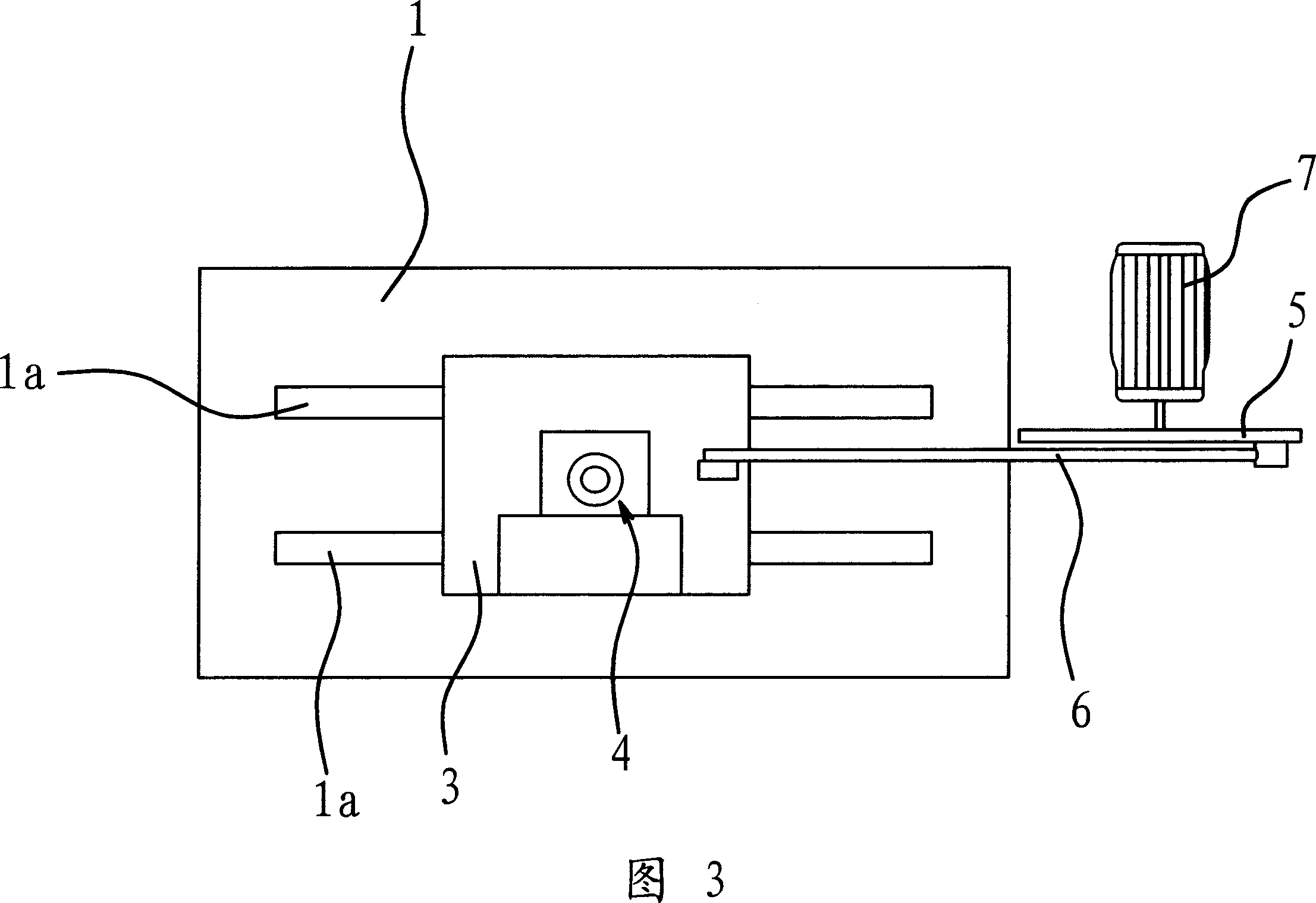
[0035] As shown in FIG. 1 , FIG. 2 and FIG. 3 , the powder molding machine includes a table 1 and a punching head 2 arranged on a frame, and the punching head 2 is located above the table 1 . The mold control device of this powder compression molding machine is just arranged on the table top 1 and is below the stamping head 2 .
[0036] It includes a mold base 3, a transmission mechanism and a guide rail 1a arranged on the table 1. The mold base 3 is placed on the guide rail 1a and can slide along the guide rail 1a. The mold base 3 is equipped with a mold core 4.
[0037] Transmission mechanism is made up of rotating disk 5 and connecting rod 6, is also provided with the power mechanism that makes transmission mechanism action on transmission mechanism, and power mechanism is motor 7. The rotating shaft of motor 7 is fixedly connected at the center of rotating disk 5 one side, and one end of above-mentioned connecting rod 6 is hinged on the non-center position of rotating disk...
Embodiment 2
[0046] The structure and principle of this embodiment are basically the same as that of Embodiment 1. The difference is that the power mechanism is a gear set 16, and the outer side of the above-mentioned turntable 5 has teeth, that is to say, the turntable 5 is a gear, and the turntable 5 and the gear set A driven gear 16a in 16 is meshed, as shown in FIG. 4 .
[0047] It can be seen that the gear set 16 can drive the turntable 5 to rotate together during operation.
Embodiment 3
[0049] The structure and principle of this embodiment are basically the same as that of Embodiment 1. The difference is that the transmission mechanism is composed of a power cam 17, a transmission rod 18, a holding spring 20 and a stopper 1b, and the power cam 17 is fixedly connected to the rotating shaft of the motor. Above, the block body 1b is fixedly connected with the table top 1, and one end of the transmission rod 18 passes through the block body 1b and is fixedly connected with the above-mentioned mold seat 3, and the supporting spring 20 is sleeved on the transmission rod 18 and its two ends respectively act on the On the rod 18 and the blocking body, the other end of the transmission rod 18 abuts against the power cam 17 under the elastic force of the holding spring 20 , as shown in FIG. 5 .
[0050] Since the blocking body 1b is fixedly connected to the table top 1, the two ends of the holding spring 20 act on the blocking body 1b and the transmission rod 18 respect...
PUM
 Abstract
Description
Claims
Application Information
 - Generate Ideas
- Intellectual Property
- Life Sciences
- Materials
- Tech Scout
- Unparalleled Data Quality
- Higher Quality Content
- 60% Fewer Hallucinations
Browse by: Latest US Patents, China's latest patents, Technical Efficacy Thesaurus, Application Domain, Technology Topic, Popular Technical Reports.
© 2025 PatSnap. All rights reserved.Legal|Privacy policy|Modern Slavery Act Transparency Statement|Sitemap|About US| Contact US: help@patsnap.com


