Apparatus for cutting of an extruded strand of plastically deformable material, preferably of clay

A technology for cutting devices and deformed materials, applied to ceramic molding machines, manufacturing tools, etc., can solve problems such as abnormal work, difficulty in guiding the lateral movement of the clamping frame, and shortened service life, so as to check or eliminate faults and improve reliability. Effect of proximity, small cutting speed

Inactive Publication Date: 2007-05-09
德国汉斯林格设备制造及工艺技术集团有限公司
View PDF0 Cites 3 Cited by
  • Summary
  • Abstract
  • Description
  • Claims
  • Application Information

AI Technical Summary

Problems solved by technology

In this structure, the clamping frame, which is arranged on both sides and holds the end of the cutting wire, is raised arcuately when it performs the same forward and backward movement, which is limited by the arcuate swing of the hinged rod
This not only results in a transverse movement length for the clamping frame and cutting wire which is longer than would be required for the corresponding transverse dimension of the relative strip, but also results in a relatively large transverse dimension for the device or structural height, and since the lateral part of the arc movement is not required, it also affects the cutting efficiency of the device
[0006] The disadvantage of this known device is also that the performance of the clamping frame and the transverse transmission arranged on both sides of the channel is limited by the vertical transverse plane of the point of tangential action between the hinged rod and the clamping frame
Although this shortens the structure of the transverse drive in the conveying direction, it makes it difficult to guide the transverse movement of the clamping frame and tilts the clamping frame in the transverse guide
This can also lead to malfunction, increased loading and wear on the guide surfaces, reducing service life
Although it is conceivable to improve the guidance of the lateral guide by relatively lengthening it, this would lead to a considerable increase in the structure of the device in the lateral direction

Method used


Image

  • Apparatus for cutting of an extruded strand of plastically deformable material, preferably of clay
  • Apparatus for cutting of an extruded strand of plastically deformable material, preferably of clay
  • Apparatus for cutting of an extruded strand of plastically deformable material, preferably of clay

Examples


Embodiment Construction

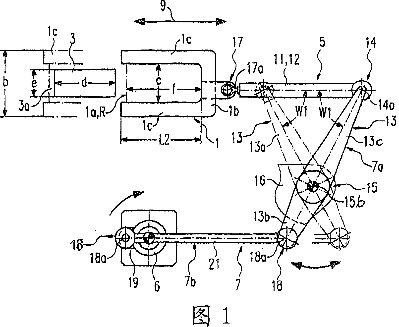
[0033] The essential part of the device shown in a simplified form is the holding frame 1 for at least one cutting line 1 a , which is shown in a simplified form of intersection, and which is fastened end-to-side in a manner not shown. The holding frame 1 and the cutting line 1a are arranged laterally offset in such a way that the holding frame 1 and the cutting line 1a is in a position laterally offset from the illustrated initial position of the channel 3a, at which position the channel 3a is formed. For this purpose, the clamping frame 1 and the cutting line 1 a are arranged below or above the channel 3 a or laterally offset relative to the channel 3 a ( FIG. 1 ).

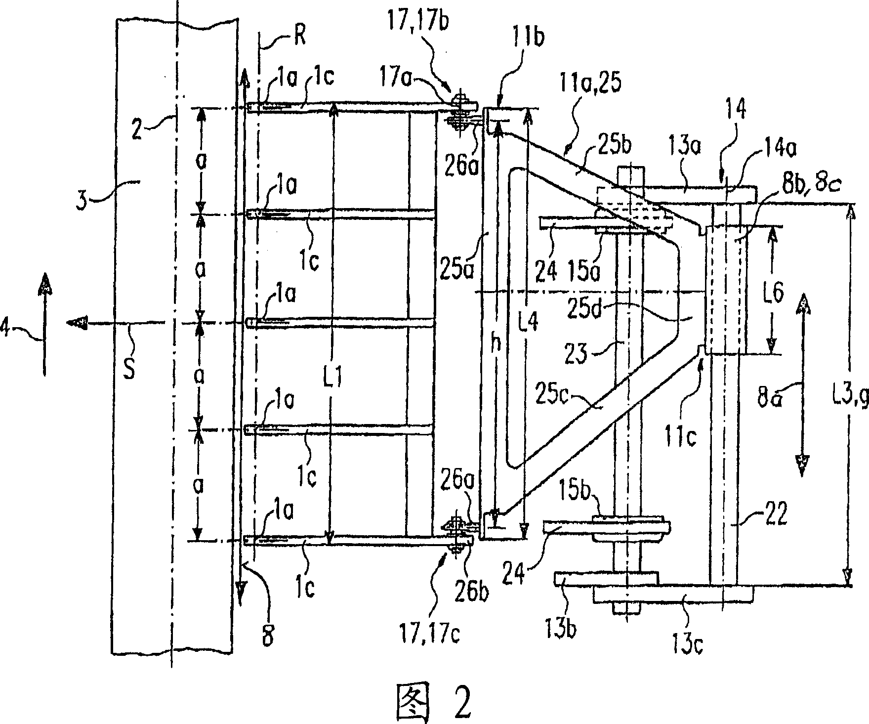
[0034] A plurality of cutting lines 1 a extending transversely to the longitudinal center axis 2 can be provided on the clamping frame 1 and form a distance a from one another extending along the longitudinal center axis 2 . For this purpose, two or more cutting wires 1a, preferably three or four or more cuttin...


PUM


Abstract

The invention relates to a cutting device for strips made of plastically deformable material, the strips are moved onto a conveyor belt in a channel extending longitudinally along the strips, and have at least one cutting line extending transversely to the channel, cutting The wire is clamped on the clamping frame at the end side, and the clamping frame makes the cutting wire move from one side of the channel to the other side and back with the longitudinal movement through the longitudinal transmission device and the transverse transmission device. The transverse transmission device includes a hinged rod A crank connecting rod, one end of the hinge rod is connected to the clamping frame through a first rotary hinge to swing around the first hinge axis, and the other end is connected to one end of at least one swing rod through a second rotary hinge to swing around the second swing axis Connected, the other end of the swing rod swings around the bearing axis and is supported on the turntable bearing. To ensure the length of the lateral movement of the clamping frame, the first and second articulation axes and the bearing axis extend parallel to the longitudinal direction of the channel, the clamping frame moves in relation to the crank rod in a longitudinal guide extending longitudinally along the channel.

Description

technical field [0001] The invention relates to a strip cutting device according to the preamble of claim 1 , 2 or 9 . Such devices are used in particular for the manufacture of blanks made of clay or similar materials in the construction industry. Background technique [0002] For this type of device, special movement conditions shall be fulfilled such that the cutting line extending transversely to the conveying direction moves transversely from one side of the conveyor belt when the longitudinal movement corresponds to the conveying speed of the strip being brought forward to the other side. As a result, strips can be cut during transport, wherein both ends of the cutting wire are clamped on the clamping frame, which is moved correspondingly by the longitudinal drive and the transverse drive. [0003] It is known that, on both sides of the strip passage, the holders for the respective ends of the cutting line move in horizontal longitudinal guides and vertical transvers...

Claims


Application Information

Patent Timeline
IPC IPC(8): B28B11/14
CPCB28B11/165
Inventor 赖纳·科克
Owner 德国汉斯林格设备制造及工艺技术集团有限公司
Why Eureka
Try Eureka