Filter device

A filter device and filter element technology, which is applied in filtration and separation, membrane filter, mobile filter element filter, etc., can solve the problems of pollution and waste water purification reaction, and achieve the effect of simple support and reliable sealing

Inactive Publication Date: 2007-05-09
HANS HUBER MASCHEN & ANLAGENBAU
View PDF1 Cites 0 Cited by
  • Summary
  • Abstract
  • Description
  • Claims
  • Application Information

AI Technical Summary

Problems solved by technology

This has the disadvantage that when the seal fails, uncleaned liquid can enter the permeate and the already cleaned liquid becomes contaminated
This leads to a severe backlash in wastewater purification

Method used


Image

  • Filter device
  • Filter device
  • Filter device

Examples


Embodiment Construction

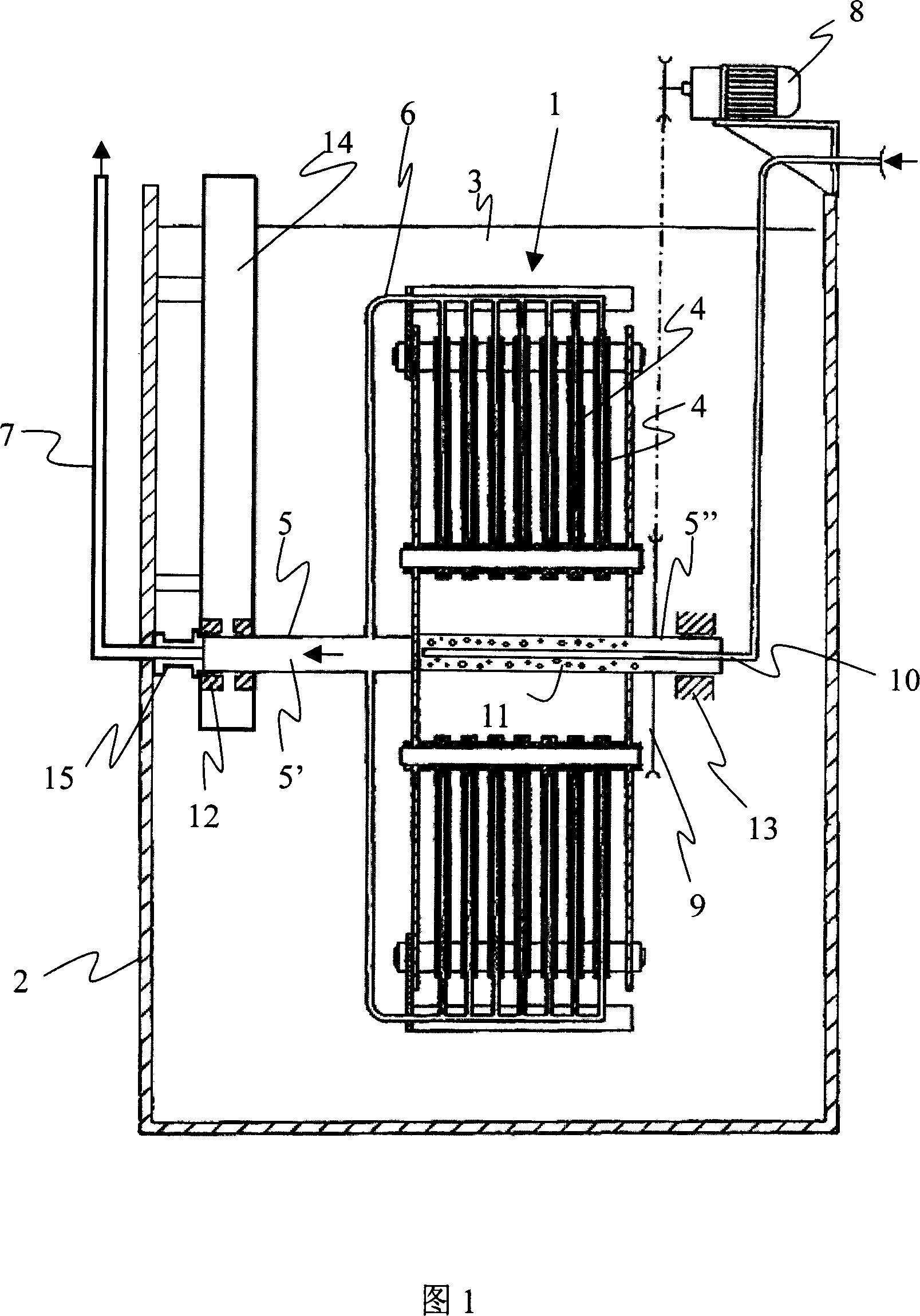
[0028] FIG. 1 shows a filter device 1 inside a container 2 containing raw liquid, in particular waste water 3 . The filter device 1 consists of several filter elements 4 arranged at intervals in a circle or polygon on a rotatably mounted hollow shaft 5 . The waste water 3 rests on the outside of the filter element 4 and is sucked through the filter element 4 into the supply line 6 . The supply line 6 leads to the hollow shaft 5 and from there is conveyed to the stationary duct 7 for removal from the container 2 .

[0029]The hollow shaft 5 together with the filter device 1 is driven by a drive motor 8 , in this example with a chain drive, which acts on a transmission gear 9 of the hollow shaft. A lance 10 through which a flushing medium, for example flushing gas or flushing liquid, is introduced is introduced into the interior of the hollow shaft 5 . The hollow shaft 5 is provided with several holes 11 in the area of ​​the lance 10, through which the flushing medium of the l...


PUM


Abstract

A filter apparatus in a container ( 2 ) containing non-clarified contaminated liquid, especially wastewater ( 3 ), for clarifying the contaminated liquid, which comprises a plurality of spaced filter elements ( 4 ) arranged in a circle or a polygon on a rotatably supported hollow shaft ( 5 ), wherein the filter elements ( 4 ) are connected to the hollow shaft ( 5 ) in order to remove clarified liquid as permeating fluid ( 16 ) through the hollow shaft ( 5 ) out of the container ( 2 ) via a stationary pipeline ( 7 ). The rotating hollow shaft ( 5 ) separates the wastewater ( 3 ) from the permeating fluid ( 16 ) via at least two sealing elements ( 17, 18 ), and a blocking medium is arranged between the sealing elements ( 17, 18 ) for separating wastewater ( 3 ) and permeating fluid ( 16 ).

Description

technical field [0001] The present invention relates to a filter device for purifying unpurified polluted liquid, especially waste water, which is composed of several hollow shafts that are rotatably supported and arranged at intervals in a circle or a polygon filter element. These filter elements are connected to a hollow shaft to pass the purified liquid as permeate through the hollow shaft and out of the container via fixed tubing. Background technique [0002] Universal filter devices are known, for example from WO 01 / 80971. Raw liquid is present in the container and is purified by the filter element of the filter unit. The purified liquid is supplied as permeate through the pipe system of the hollow shaft. The transfer of permeate from the hollow shaft to the stationary pipe takes place in a swivel bearing arranged to seal the permeate line from the raw liquid. This has the disadvantage that when the seal fails, uncleaned liquid can pass into the permeate, whereby t...

Claims


Application Information

Patent Timeline
IPC IPC(8): B01D33/21B01D33/39
CPCB01D33/21B01D2201/34B01D33/39B01D33/68
Inventor B·施塔德勒
Owner HANS HUBER MASCHEN & ANLAGENBAU
Why Eureka
Try Eureka