
Device and method for conditioning and monitoring of a saw blade

A technology of saw blade and guide device, which can be used in attachment devices of sawing machines, fine working devices, metal sawing equipment, etc., and can solve complex and labor-intensive problems.

Active Publication Date: 2007-05-02
BESI NETHERLANDS BV
View PDF0 Cites 0 Cited by
  • Summary
  • Abstract
  • Description
  • Claims
  • Application Information

AI Technical Summary

Problems solved by technology

The disadvantage of existing devices for separating electronic components is that they require rather complicated and labor-intensive operations

Method used


Image

  • Device and method for conditioning and monitoring of a saw blade
  • Device and method for conditioning and monitoring of a saw blade
  • Device and method for conditioning and monitoring of a saw blade

Examples


Embodiment Construction

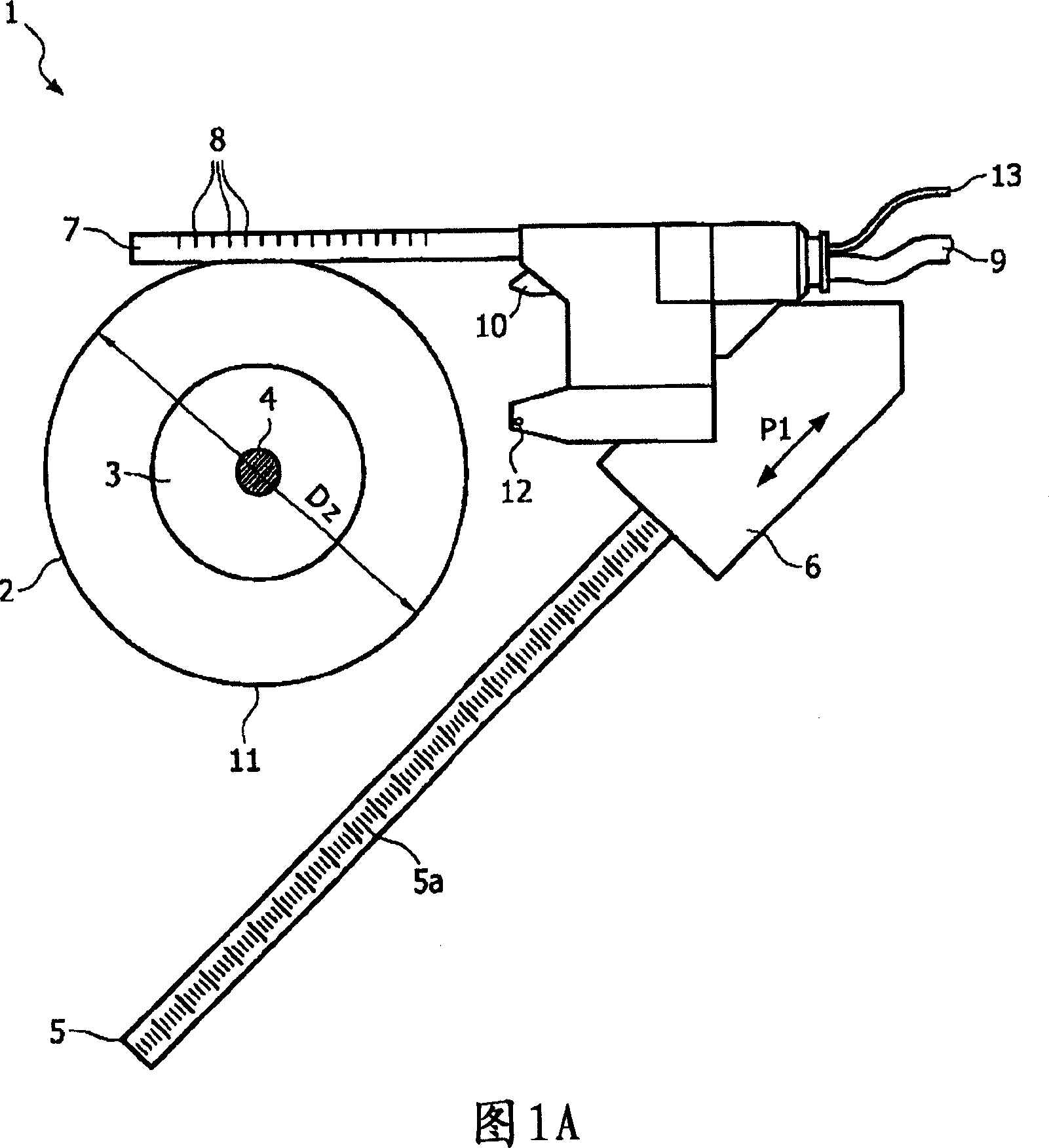
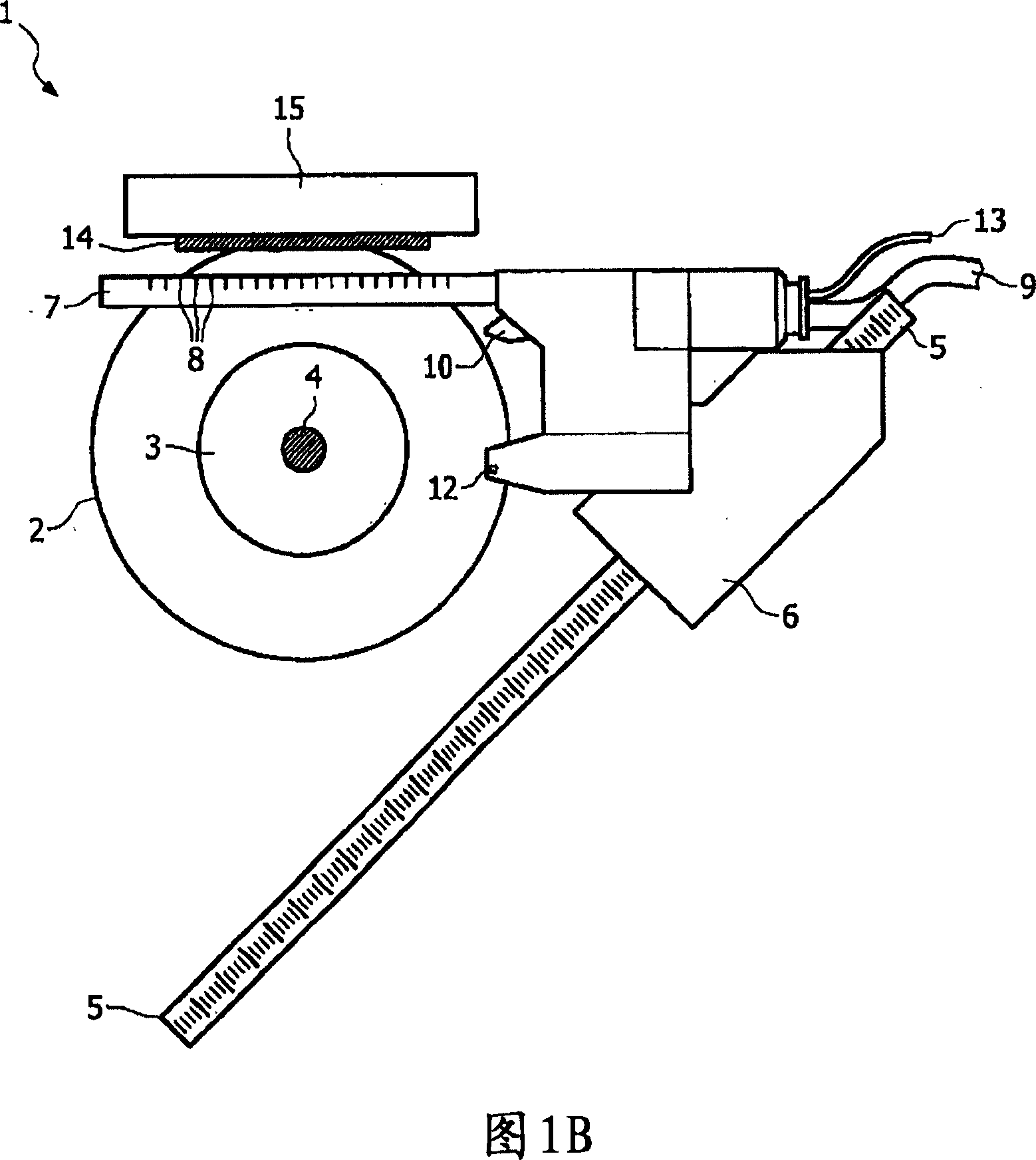
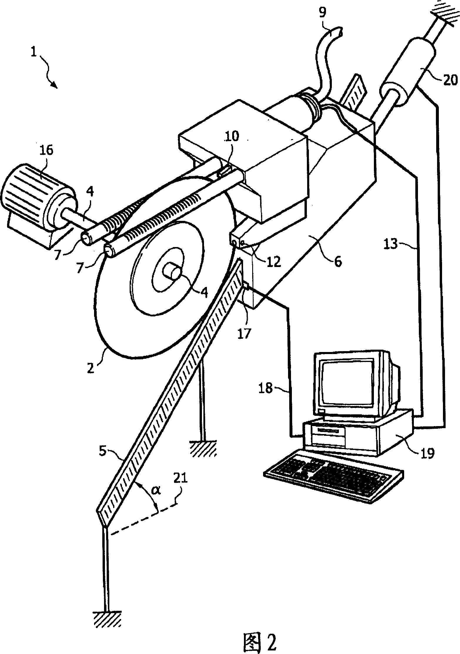
[0017] FIG. 1 shows a device 1 with a saw blade 2 for separating electronic components (not shown in this figure). The saw blade 2 is rigidly connected to a rotating drive shaft 4 with a mounting flange 3 . Located in a fixed position relative to the drive shaft 4 is a guide 5 along which the support frame 6 is movable according to the arrow P1. The support frame 6 carries a tube 7 with a slit 8 from which the liquid provided by the supply tube 9 can be sprayed. The liquid provided by the pipe 8 is used in particular to remove sawdust, as will be further elucidated in the following figures. The support frame also carries nozzles 10 from which the liquid supplied by the supply pipe 9 can also be sprayed. Alternatively, it is also possible that a separate supply for the nozzle 10 (ie separate from the supply 9 for the pipe 8 ) is connected to the device 1 . The nozzle 10 serves in particular to spray a liquid onto the circular cutting edge 11 of the saw blade 2 . The support...


PUM


Abstract

A device for separating electronic components mounted on a carrier, comprising: a rotatable saw blade (2) with a substantially circular cutting edge (11); at least one sensor (12) for detecting the substantially circular cutting edge (11); and a distributor (7, 8, 10) for the medium, wherein the sensor (12) and the distributor (7, 8, 10) are mounted on a common carrier (6), which (6) can be displaced along the guide (5) relative to the saw blade (2). The invention also relates to a method for separating electronic components mounted on a carrier.

Description

technical field [0001] The invention relates to a device for separating electronic components mounted on a carrier, the device comprising: a rotatable saw blade with a substantially circular cutting edge; at least one sensor for detecting the substantially circular cutting edge; and dispensers for media. The invention also relates to a method for separating an electronic component mounted on a carrier by displacing a rotating saw blade and the carrier with the electronic component to be separated relative to each other. Background technique [0002] Separation of electronic components, such as in particular semiconductors, takes place in particular by machining the carrier on which the electronic components are mounted using a rotating saw blade. Such carriers are often also referred to as leadframes, semiconductor wafers or plates. During the processing operation, other materials may also be separated at the same time, such as molding material (in the form of cured epoxy ...

Claims


Application Information

Patent Timeline
IPC IPC(8): B23D59/00B28D5/00
CPCB23D59/001B28D5/0076B23D59/00B28D5/00
Inventor W·G·L·范斯普朗G·A·因特维尔德
Owner BESI NETHERLANDS BV
Learn More