Moving image display device and method
A dynamic image and display device technology, which is applied in image communication, static indicators, cathode ray tube indicators, etc., can solve the problems of unsmooth image display, difficulty in improving the display speed of dynamic images, and increased costs, so as to suppress dynamic images Effects of flickering, smooth dynamic screen display, and reduction of memory capacity
- Summary
- Abstract
- Description
- Claims
- Application Information
AI Technical Summary
Problems solved by technology
Method used
Image
Examples
Embodiment 1
[0031] (A-1) Hardware composition of the projector:
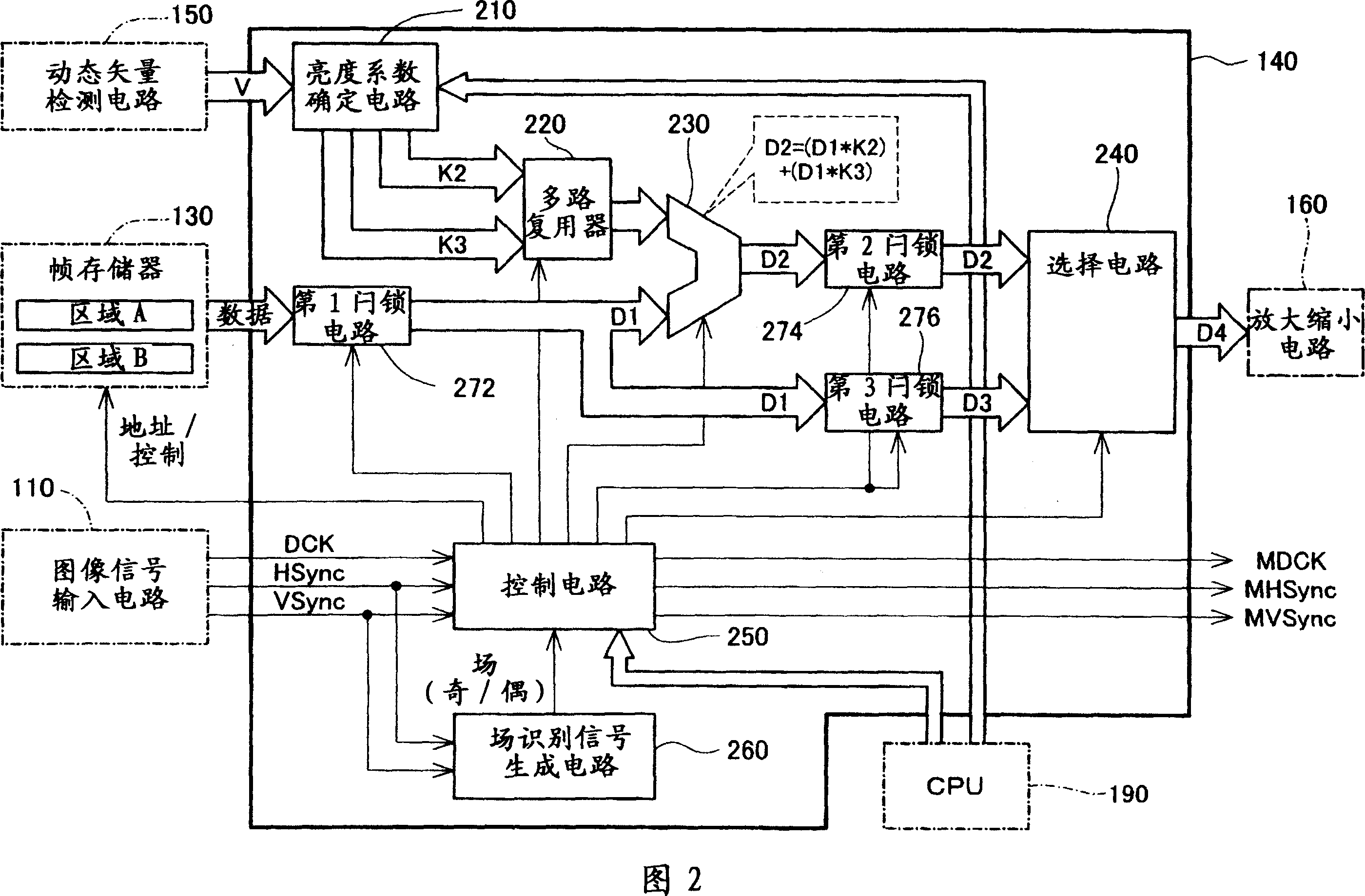
[0032] (A-2) The composition and operation of the intermediate frame generation circuit:
[0033] (A-3) Effect:
Embodiment 2
[0035] C. Variations:
[0036] A. Embodiment 1:
[0037] (A-1) Hardware composition of the projector:
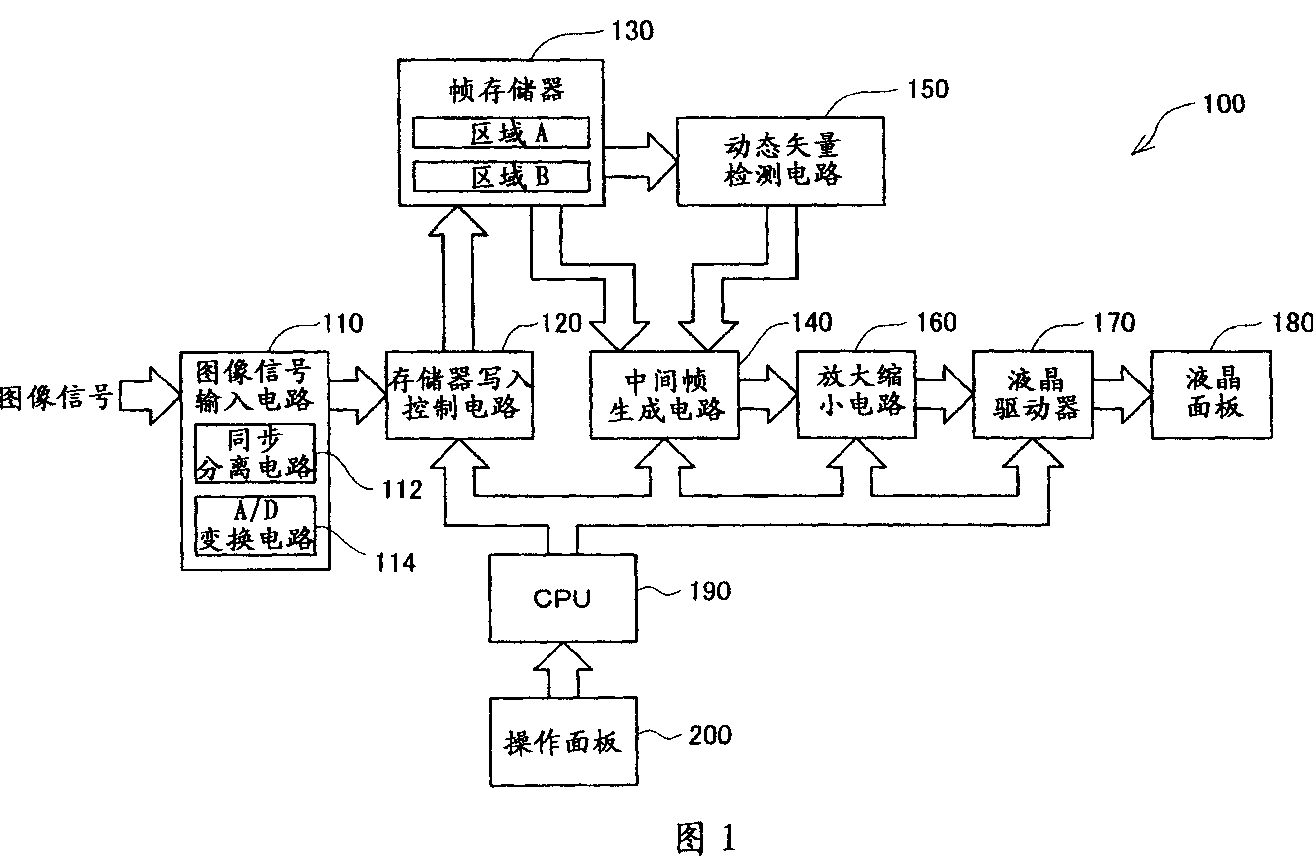
[0038] FIG. 1 is a block diagram showing a hardware configuration of a projector 100 as an embodiment of the moving image display device of the present application. This projector 100 has a function of displaying a moving image at least twice the frame rate of the original moving image. A specific configuration for displaying at twice or more the frame rate will be described in detail later.
[0039] As shown in the figure, the projector 100 of this embodiment has an image signal input circuit 110, a memory writing control circuit 120 connected to the image signal input circuit 110, and a frame memory 130 connected to the memory writing control circuit 120. , the motion vector detection circuit 150 that is connected with the frame memory 130, the intermediate frame generation circuit 140 that is connected with the frame memory 130 and the motion vector detection circuit 1...
example 1
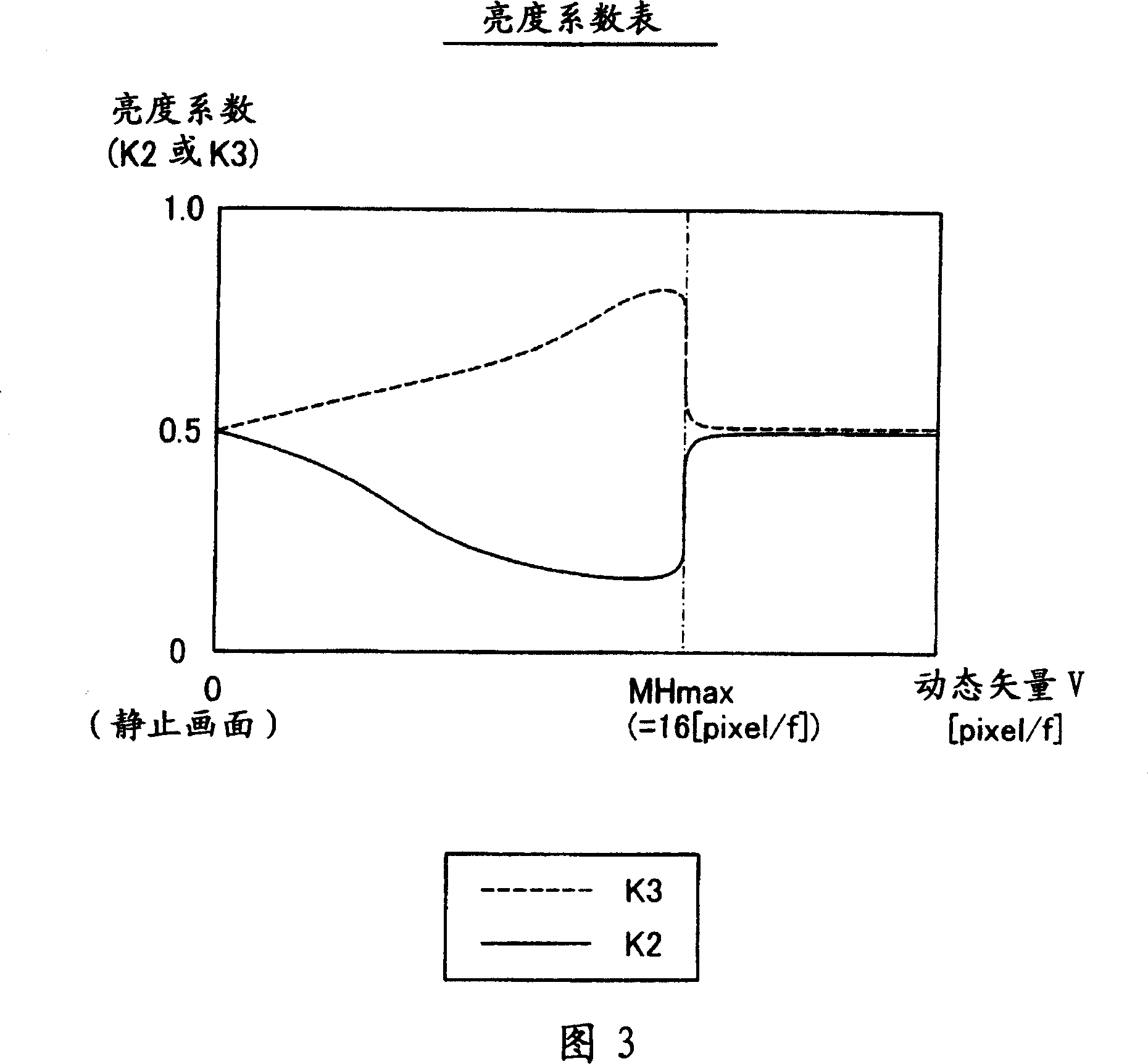
[0084] Next, a modified example of the method of determining the luminance coefficients K2 and K3 will be described using FIGS. 8 to 10 . In this modified example, the luminance coefficient determination circuit 210 shown in FIG. 2 determines the luminance coefficients K2 and K3 according to the number n of intermediate frame images to be generated and the characteristics of the sine wave regardless of the motion vector V.
[0085] In this modified example, when the number of intermediate frame images generated by the synthesis circuit 230 is set by the CPU 190, the luminance coefficient determination circuit 210 determines the number of intermediate frame images for each intermediate frame image according to the table shown in FIG. 8 . The angle θ(rd) (0≤θ≤π) of the brightness coefficients K2 and K3 is obtained. In the table shown in FIG. 8 , values obtained by dividing the interval from 0 to π by the number of intermediate frame images are defined. According to this table...
PUM
 Abstract
Description
Claims
Application Information
 - Generate Ideas
- Intellectual Property
- Life Sciences
- Materials
- Tech Scout
- Unparalleled Data Quality
- Higher Quality Content
- 60% Fewer Hallucinations
Browse by: Latest US Patents, China's latest patents, Technical Efficacy Thesaurus, Application Domain, Technology Topic, Popular Technical Reports.
© 2025 PatSnap. All rights reserved.Legal|Privacy policy|Modern Slavery Act Transparency Statement|Sitemap|About US| Contact US: help@patsnap.com


