Moving image display device and method for moving image display

A dynamic image and display device technology, applied in image communication, static indicator, image data processing, etc., can solve problems such as increased cost, inability to smooth image display, and virtual images, and achieves reduction of memory capacity, suppression of dynamic image flicker, The effect of increased processing speed

Inactive Publication Date: 2007-05-09
SEIKO EPSON CORP
View PDF4 Cites 9 Cited by
  • Summary
  • Abstract
  • Description
  • Claims
  • Application Information

AI Technical Summary

Problems solved by technology

[0006] However, in the above-mentioned conventional technology, since a new intermediate frame needs to be generated from two frame images, the calculation processing is huge, and it is difficult to increase the display speed of the dynamic picture.
In addition, to generate a new intermediate frame, it is necessary to ensure a large frame memory capacity, which is the main cause of cost increase
In addition, when switching between the display method of a moving image and a still image, there may be a case where a virtual image appears when the display method is switched, and the image cannot be displayed smoothly.

Method used


Image

  • Moving image display device and method for moving image display
  • Moving image display device and method for moving image display
  • Moving image display device and method for moving image display

Examples


Embodiment 1

[0035] (A-1) Hardware composition of the projector:

[0036] (A-2) The composition and operation of the intermediate frame generation circuit:

[0037] (A-3) Effect:

Embodiment 3

[0040] D. Variations:

[0041] A. Embodiment 1:

[0042] (A-1) Hardware composition of the projector:

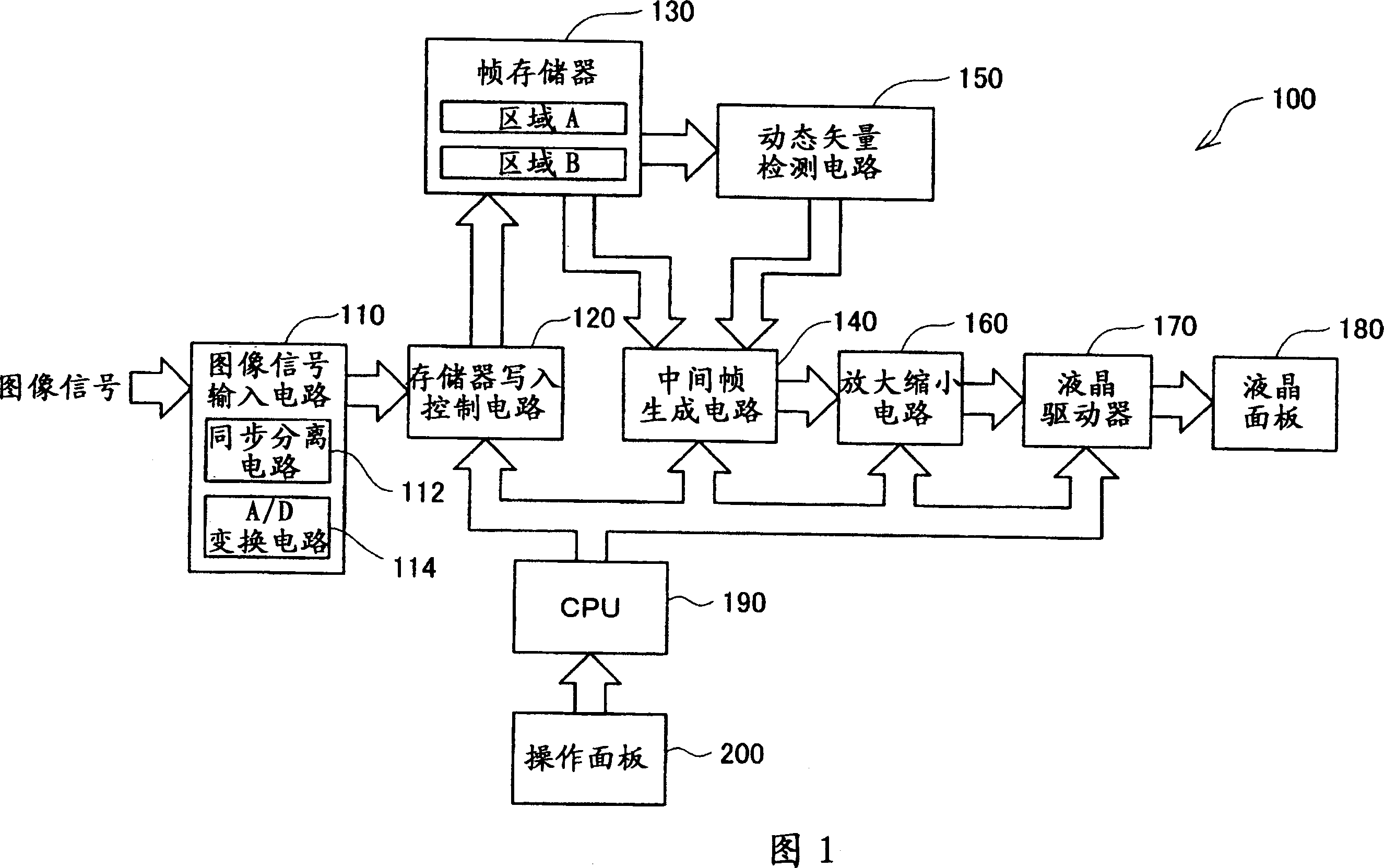
[0043] FIG. 1 is a block diagram showing a hardware configuration of a projector 100 as an example of a video display device of the present application. This projector 100 has a function of displaying a moving image at least twice the frame rate of the original moving image. A specific configuration for displaying at twice or more the frame rate will be described in detail later.

[0044] As shown in the figure, the projector 100 of this embodiment has an image signal input circuit 110, a memory writing control circuit 120 connected to the image signal input circuit 110, and a frame memory 130 connected to the memory writing control circuit 120. , the motion vector detection circuit 150 that is connected with the frame memory 130, the intermediate frame generation circuit 140 that is connected with the frame memory 130 and the motion vector detection circuit 150, the enla...

example 1

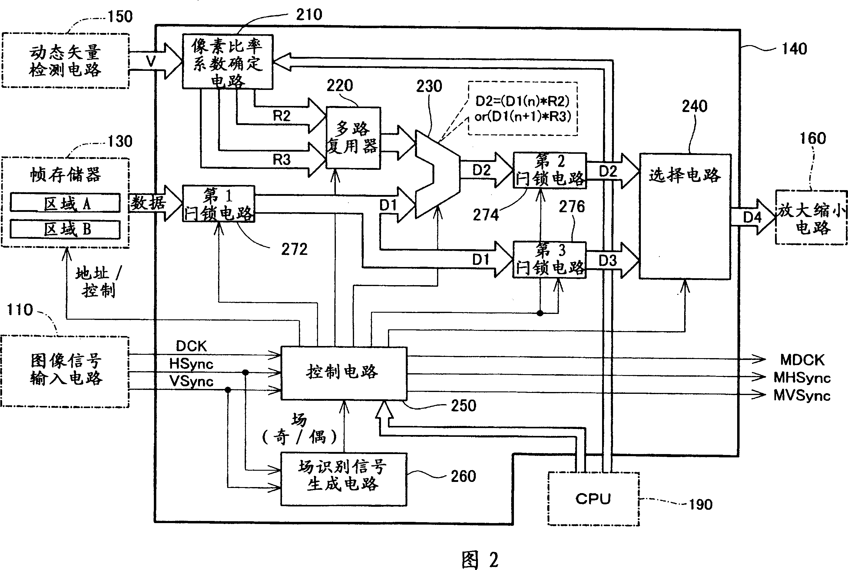
[0095] Next, a modified example of the method of determining the pixel ratio coefficients R2 and R3 will be described using FIGS. 9 to 11 . In this modified example, the pixel ratio coefficient determination circuit 210 shown in FIG. 2 determines the values ​​of the pixel ratio coefficients R2 and R3 according to the number n of intermediate frame images to be generated and the characteristics of the sine wave regardless of the motion vector V.

[0096] In this modified example, when the number of intermediate frame images generated by the synthesis circuit 230 is set by the CPU 190, the pixel ratio coefficient determination circuit 210 determines the number of intermediate frame images to be used for each intermediate frame image according to the table shown in FIG. 9 . The angle θ(rd) (0≤θ≤π) of the pixel ratio coefficients R2 and R3 is obtained. In the table shown in FIG. 9 , values ​​obtained by dividing the interval from 0 to π by the number of intermediate frame images a...


PUM


Abstract

In the moving image display device of the invention, a synthesis circuit inputs signals representing specified values of pixel rate factors R 2 and R 3 from a pixel rate factor specification circuit, while inputting overscanned frame image data D 1 in the units of pixels from a 1st latch circuit. The synthesis circuit extracts a preset number of pixels corresponding to the specified value of the pixel rate factor R 2 from a prior frame image, while extracting a preset number of pixels corresponding to the specified value of the pixel rate factor R 3 from a latter frame image. The positions of pixels to be extracted from the latter frame image are complementary to the positions of pixels to be extracted from the prior frame image. The synthesis circuit combines the extracted pixels of the prior frame image with the extracted pixels of the latter frame image by a logical OR operation to generate intermediate frame image data D 2. This technique of the invention is significantly simpler than the prior art technique but still effectively prevents flicker in a moving image to ensure smooth display of the moving image.

Description

technical field [0001] The present invention relates to a technique for displaying a moving image by continuously displaying a plurality of frame images, and specifically relates to a technique for synthesizing a plurality of frame images to generate intermediate frame images. Background technique [0002] Conventionally, for example, when displaying images on moving image display devices such as CRTs and televisions, flickering may appear on the entire screen when the refresh rate is lower than 60 Hz. However, even when a sufficient refresh rate can be ensured, when a moving image of a moving object moving on the screen is displayed, flickering may not appear on the entire screen, but only on a portion of the moving object on the screen. Such flickering is hereinafter referred to as "moving screen flickering". This phenomenon often occurs, for example, when displaying a moving image in which a person, a vehicle, an airplane, etc. move within a screen at a constant speed, o...

Claims


Application Information

Patent Timeline
Patent Type & Authority Applications(China)
IPC IPC(8): G09G5/377G09G3/20G09G3/36G09G5/00G09G5/36H04N5/21H04N5/262
CPCG09G2320/0247G09G2340/10G09G2340/16H04N7/0132G06T3/4007G09G3/001G09G3/3611G09G3/20G09G5/00H04N5/14
Inventor 竹内启佐敏佐川隆博饭坂英仁
Owner SEIKO EPSON CORP
Why Eureka
Try Eureka