
Electronic device and its fastener linking structure

A hook-to-hook connection and linkage technology, which is applied in the direction of electrical digital data processing, instruments, digital data processing parts, etc., can solve the problems of exposed hooks, easy deformation and damage of lock components

Active Publication Date: 2007-05-02
ASUSTEK COMPUTER INC
View PDF0 Cites 13 Cited by
  • Summary
  • Abstract
  • Description
  • Claims
  • Application Information

AI Technical Summary

Problems solved by technology

[0006] In view of the defects in the above-mentioned existing electronic devices and their snap-hook interlocking structures, the inventors, based on years of rich practical experience and professional knowledge engaged in the design and manufacture of such products, and in conjunction with the application of academic theories, actively researched and innovated, with a view to creating An electronic device and its hook interlocking structure with a new structure that can solve the disadvantages of the hook of the lock assembly being exposed, easily deformed and damaged, and can improve the general existing electronic device and its hook interlocking structure, making it more Practicality

Method used


Image

  • Electronic device and its fastener linking structure
  • Electronic device and its fastener linking structure
  • Electronic device and its fastener linking structure

Examples


Embodiment Construction

[0046] In order to further explain the technical means and effects of the present invention to achieve the intended purpose of the invention, in conjunction with the drawings and preferred embodiments, the specific implementation, structure, Features and their functions are described in detail below.

[0047] Through the description of the specific implementation mode, when the technical means and functions adopted by the present invention to achieve the predetermined purpose can be obtained a deeper and more specific understanding, but the accompanying drawings are only for reference and description, and are not used to explain the present invention be restricted.

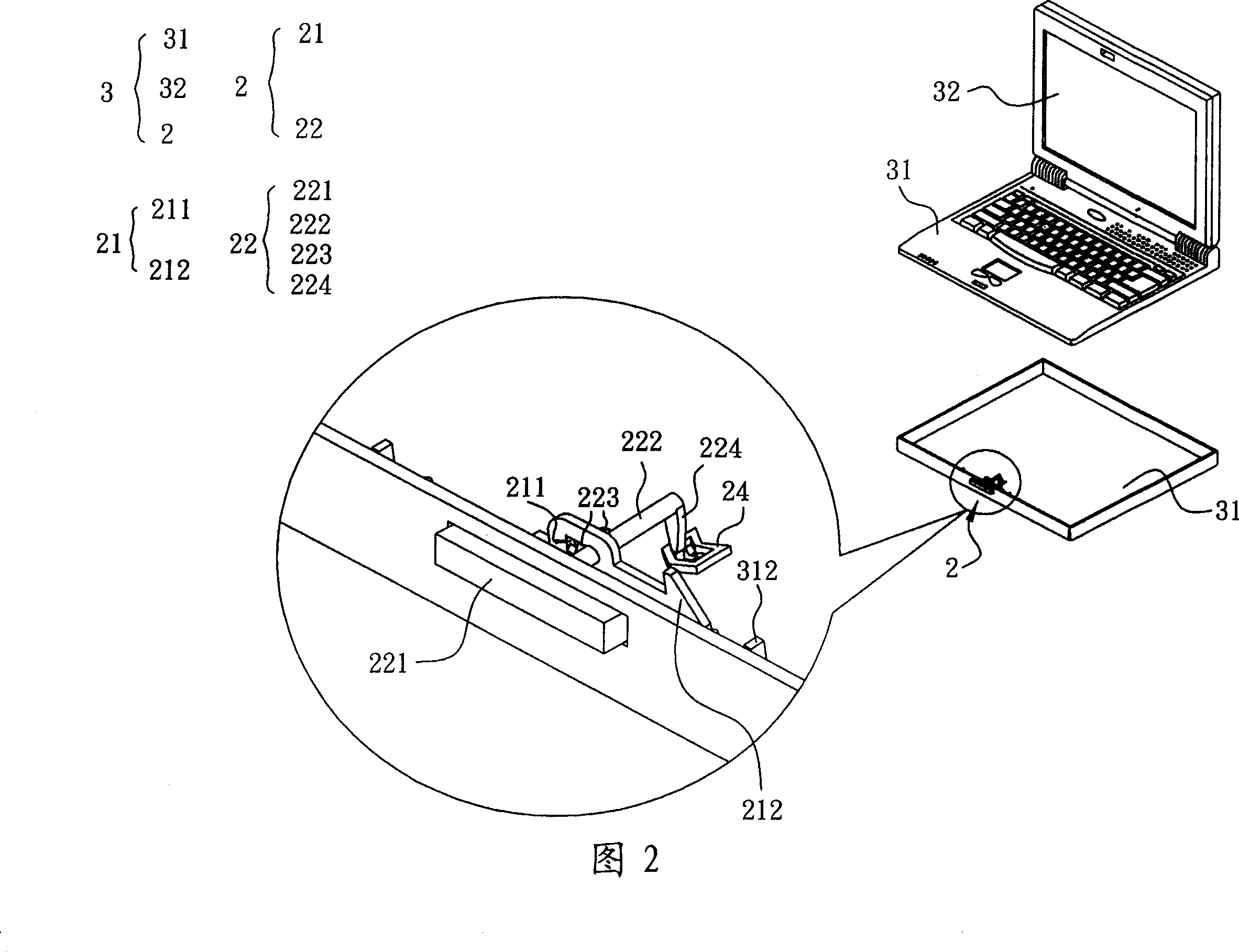
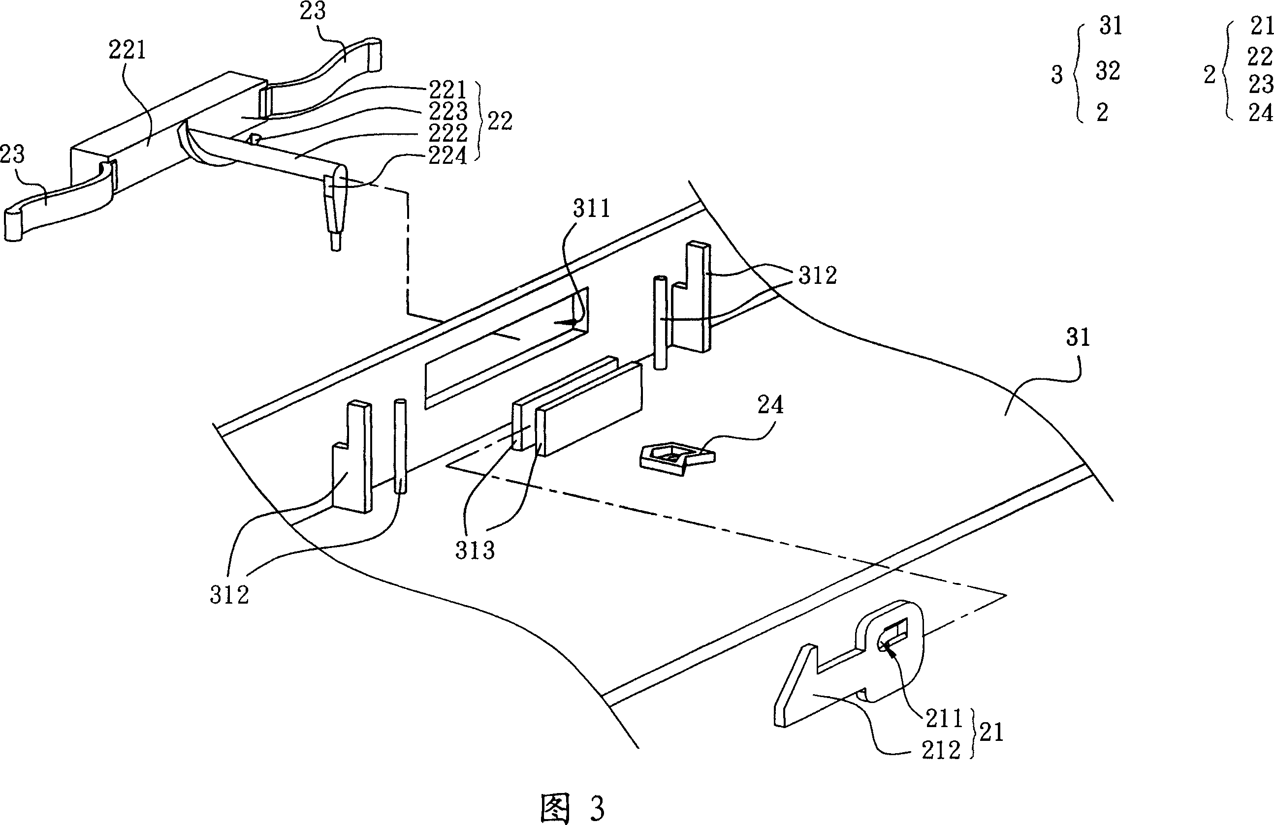
[0048] Referring to FIG. 2 and FIG. 3 , the electronic device 3 according to a preferred embodiment of the present invention includes a first housing 31 , a second housing 32 and a hook interlocking structure 2 . Wherein, the first housing 31 has an opening 311, the second housing 32 has a clamping portion 321 (a...


PUM


Abstract

A hook linkage structure is pin jointing said linkage structure separately on the first shell with an opening and on the second shell with a holding unit, forming said linkage structure by a check-fastening element and a pressing down element as well as an elastic element. It features that said check-fastening element in moved to the first position and is checked with holding unit on the second shell to each other when said pressing down element is moved towards to the first direction by an external force.

Description

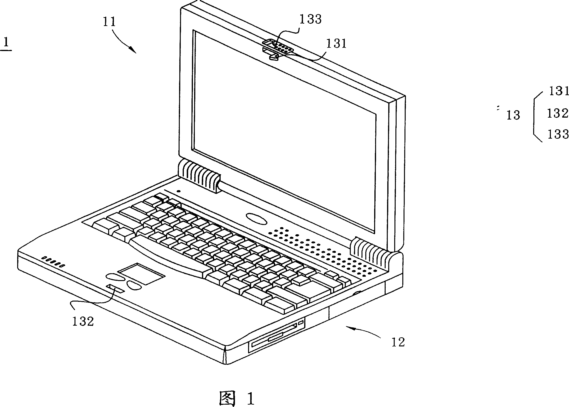
technical field [0001] The present invention relates to a hook structure, in particular to an electronic device which can be used for the hook structure of an electronic device and a hook interlocking structure (ELECTRONIC DEVICE AND LATCH STRUCTURETHEREOF). Background technique [0002] Notebook computers (i.e. computers) are mainly composed of a host and a liquid crystal display. In order to ensure that the liquid crystal display will not be opened arbitrarily during carrying, or to facilitate daily storage, a lock assembly is installed on the liquid crystal display and the main base. to lock the notebook computer. [0003] Please refer to FIG. 1 , which is a structural schematic view showing a conventional electronic device and a lock assembly. The conventional electronic device 1 has a liquid crystal display 11 , a host 12 and a locking component 13 . Wherein, the lock assembly 13 includes a hook 131 , a groove 132 and a push button 133 . When the liquid crystal displ...

Claims


Application Information

Patent Timeline
IPC IPC(8): G06F1/16
Inventor 王陈升
Owner ASUSTEK COMPUTER INC
Learn More