Device for suppressing pulsated impact of slurry flow in concrete pump vehicle
A concrete pump truck, pulsating impact technology, applied in the direction of unloading device, gas/liquid distribution and storage, pipeline system, etc., can solve the problems of damage to the boom mechanism, low natural frequency of the system, strong vibration of the boom, etc., to achieve convenient Maintenance, simple and compact structure, and the effect of suppressing boom vibration
- Summary
- Abstract
- Description
- Claims
- Application Information
AI Technical Summary
Problems solved by technology
Method used
Image

Examples
Embodiment 1
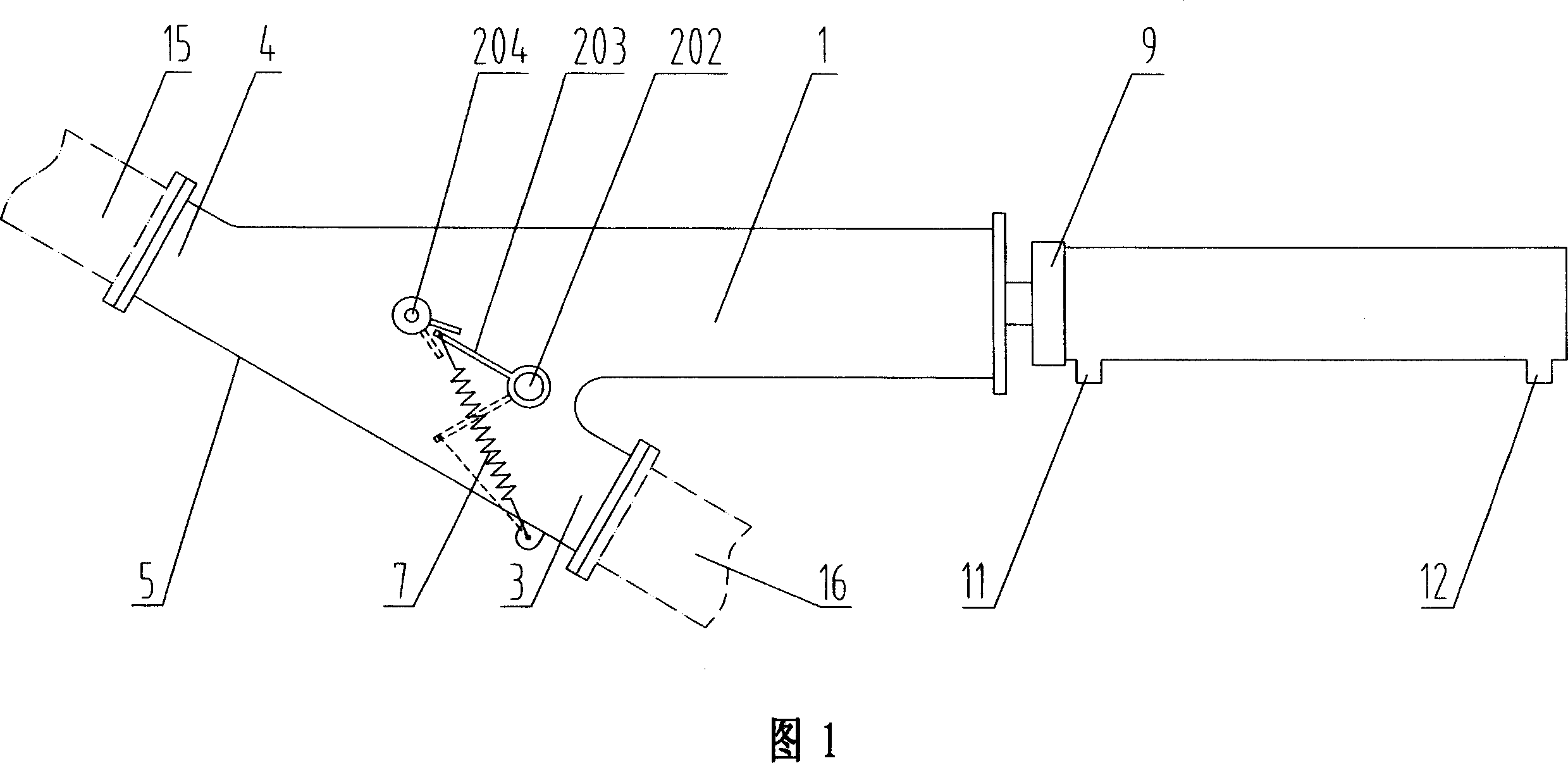
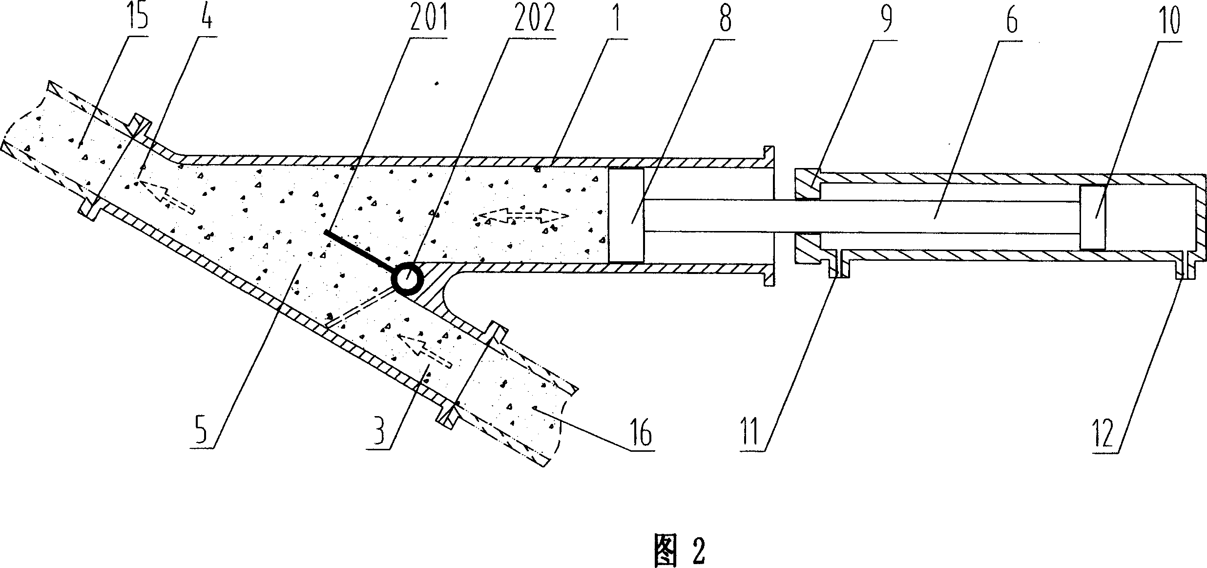
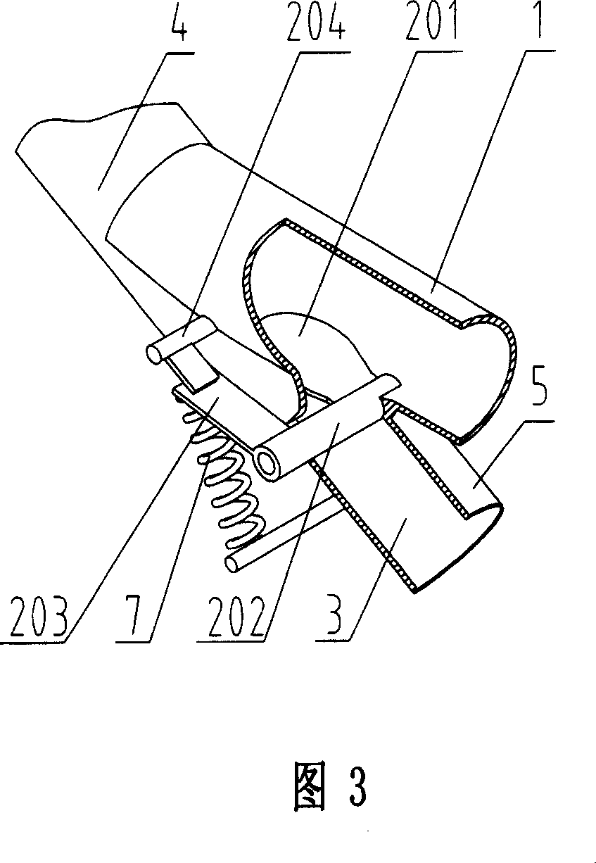
[0051]Embodiment 1: as shown in Fig. 1, Fig. 2 and Fig. 3, the present invention is used for suppressing the device of the pulsation impact of mixing fluid in the concrete pump truck, and it comprises conveying channel 5, feeding cylinder 1 and control mechanism, feeding Cylinder 1 is kept in communication with feeding passage 5, feeding piston 8 and feeding piston rod 6 are arranged in feeding feeding cylinder 1, feeding piston rod 6 is connected with the control mechanism, feeding cylinder 1 and feeding feeding passage 5 An on-off valve is provided between the ports 3 to prevent the mixed slurry fluid from flowing back. The inner diameter of feeding cylinder 1 is different from the inner diameter of feeding port 3 and discharging port 4, so as to ensure that the feeding cylinder 1 can not be closed when the on-off valve is overturned. The feeding channel 5 and the feeding port 3 are connected with the lower feeding pipe 16 at the hopper end of the concrete pump truck, and th...
Embodiment 2
[0054] Embodiment 2: The structure of this embodiment is roughly the same as that of Embodiment 1, except that the on-off valve is a rotary valve located in the delivery passage 5, and the rotary valve includes a rotary valve body 205 and a rotary shaft 206, which rotate The shaft 206 is installed on the material delivery channel 5, and the rotary valve body 205 is installed on the rotary shaft 206. The rotary valve body 205 can rotate with the rotary shaft 206 to complete the opening and closing of the material delivery channel 5. Referring to Fig. 6 and Fig. 7, the rotary valve body 205 is hemispherical or spherical. When the feeding port 3 feeds material and the feeding piston 8 sucks the material, the rotary valve body 205 rotates under the drive of the rotary shaft 206 to open the feeder. Material channel 5, the inner side wall of delivery channel 5 can be provided with the accommodating part of rotary valve body 205; 206 rotates, closes the passage between feed inlet and...
Embodiment 3
[0055] Embodiment 3: The structure of this embodiment is roughly the same as that of Embodiment 1, the difference is that the on-off valve is a flat valve 208, a chute 51 is provided on the delivery channel 5, and the flat valve 208 is inserted in the chute 51 . 9 and 10, the flat valve 208 is provided with a communication hole 207, and the flat valve 208 can slide freely in the chute 51 on the feeding channel 5. When the feeding port 3 feeds, the feeding piston 8 sucks When feeding, the communication hole 207 on the flat valve 208 is kept in communication with the feeding channel 5. When the feeding port 3 stops feeding and the feeding piston 8 sucks the material, the flat valve 208 slides in the direction shown by the arrow in the figure to close the inlet. A section of feed passage 5 at the feed port 3. Referring to shown in Figure 11, the flat valve 208 can slide freely in the chute 51 on the feeding passage 5, when the feeding port 3 feeds, and when the feeding piston 8 ...
PUM
 Abstract
Description
Claims
Application Information
 - Generate Ideas
- Intellectual Property
- Life Sciences
- Materials
- Tech Scout
- Unparalleled Data Quality
- Higher Quality Content
- 60% Fewer Hallucinations
Browse by: Latest US Patents, China's latest patents, Technical Efficacy Thesaurus, Application Domain, Technology Topic, Popular Technical Reports.
© 2025 PatSnap. All rights reserved.Legal|Privacy policy|Modern Slavery Act Transparency Statement|Sitemap|About US| Contact US: help@patsnap.com