


Quick Research
Generate reliable direction feasibility study reports for your R&D in just a few steps.

Technical Q&A
Discover and master advanced knowledge NOW. Basics, ideas, possibilities, all at once.

Find Solutions
As an expert in R&D theories, this can generate solutions to your technical problems instantly.

Evaluate Feasibility
Analyze your overall solution with one click, know your potential R&D risks in advance.

Monitor Landscape
Get weekly tech updates, stay abreast of the latest tech innovations and key insights.
Method and system for remote-maintaining JTAG device in ATCA
A remote maintenance and device technology, applied in the transmission system, digital transmission system, electrical components, etc., can solve the problem of remote upgrade of single-board JTAG device scanning and detection of hard-to-load files, and achieve the effect of reducing maintenance costs
- Summary
- Abstract
- Description
- Claims
- Application Information
AI Technical Summary
Problems solved by technology
Method used
Image

Examples
Embodiment 1
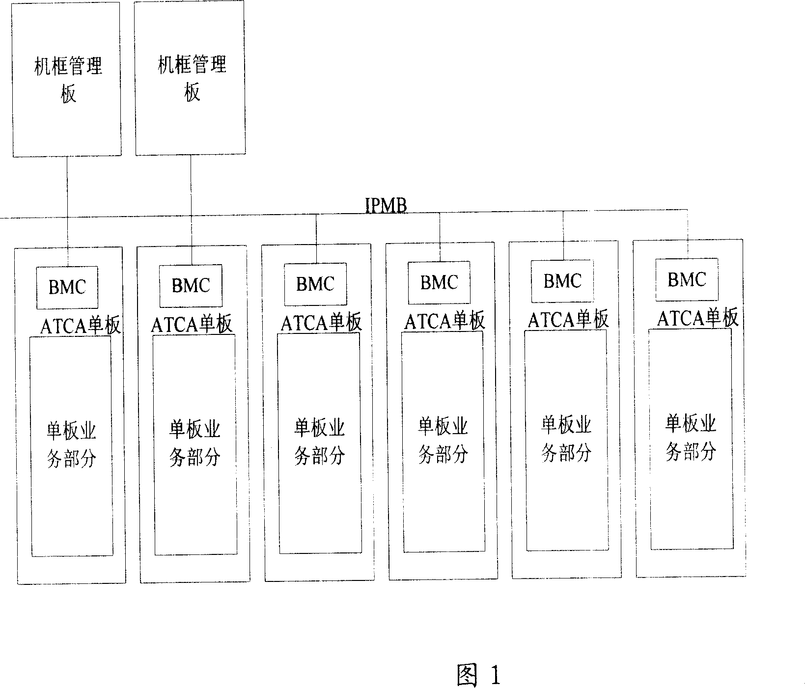
[0031] The system frame diagram of Embodiment 1 of the present invention is shown in Figure 5, including:
[0032] The chassis management board includes a storage module and a control module (CPU) that store the target files that need to be loaded. The control module is used to read the target files that need to be loaded from the storage chip and then write them to the BMC module of the ATCA single board through the IPMB bus. in the memory of
[0033] The single-board BMC module includes a controller (single-chip microcomputer), which is used to control the writing of the target file in the memory of the BMC module to the JTAG device or JTAG chain of the single-board;
[0034] The single-board BMC module also includes a memory (FLASH or other memory chips), which is used to store the written target file that needs to be loaded.
[0035] The system described in this embodiment also includes a logic device or a JTAG bridge, which is used to communicate with a JTAG device or a ...
Embodiment 2
[0041] The system architecture of this embodiment is basically the same as that of Embodiment 1, except that the logic device in Embodiment 1 is a JTAG bridge in this embodiment, which has the function of selecting which JTAG interface device to connect to.
[0042] The process of loading software on a single-board JTAG device or JTAG chain is shown in Figure 6 and Figure 8, and the main steps are as follows:
[0043] 1. The chassis management board is connected to the single-chip microcomputer (or other controller) of the BMC through the IPMB bus. The CPU of the chassis management board reads the target file to be loaded from its own storage module, and then writes the target file to be loaded into into a FLASH (or other memory) of the BMC module;
[0044] 2. The single-chip microcomputer (or other controller) in the single-board BMC module writes the target file from the FLASH (or other memory chip) to the JTAG device or JTAG chain, and uses the I / O interface of the single-chi...
Embodiment 3
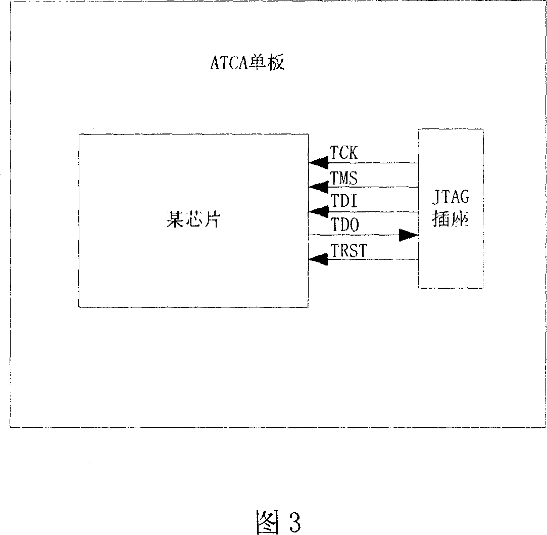
[0047] In the existing ATCA specification, for the backplane connector, a group of signals is reserved for the user to define. In this embodiment, a part of this group of signals is used to define 5 of them as standard signals of the JTAG interface, namely: TCK, TMS, TRST, TDI, and TDO signals. These five signals are routed to each ATCA board through the backplane. The TCK, TMS, TRST, and TDI signals are the output signals of the chassis management board, and TDO is the ATCA board. As shown in Figure 9, the chassis management board is connected to each ATCA board through the JTAG bus. The JTAG bus includes the above-mentioned 5 signal lines, and the 5 signals meet the JTAG standard IEEE 1149.1.
[0048] First, connect the JTAG devices on each board into a chain to form a JTAG chain. If the board has only one JTAG chain, directly connect the five signals to the JTAG chain on the board, as shown in Figure 10, to realize scanning and loading of all JTAG devices on the board.
[...
PUM
 Abstract
Description
Claims
Application Information
 - R&D Engineer
- R&D Manager
- IP Professional
- Industry Leading Data Capabilities
- Powerful AI technology
- Patent DNA Extraction
Browse by: Latest US Patents, China's latest patents, Technical Efficacy Thesaurus, Application Domain, Technology Topic, Popular Technical Reports.
© 2024 PatSnap. All rights reserved.Legal|Privacy policy|Modern Slavery Act Transparency Statement|Sitemap|About US| Contact US: help@patsnap.com