Dynamic 3D laser scanning testing head

A three-dimensional laser, scanning probe technology, applied in measurement devices, optical devices, instruments, etc., can solve problems such as being unsuitable for real-time detection, and achieve the effect of avoiding scanning blind spots and strong competitiveness

Inactive Publication Date: 2007-04-18
DALIAN MARITIME UNIVERSITY
View PDF0 Cites 16 Cited by
  • Summary
  • Abstract
  • Description
  • Claims
  • Application Information

AI Technical Summary

Problems solved by technology

In the past, the three-dimensional coordinate measuring machine fixed the three-dimensional laser scanning probe on the workpiece, and obtained the complete three-dimensional data of the surface of the workpiece by changing the spatial position of the workpiece to be measured. real-time detection

Method used


Image

  • Dynamic 3D laser scanning testing head
  • Dynamic 3D laser scanning testing head
  • Dynamic 3D laser scanning testing head

Examples


Embodiment Construction

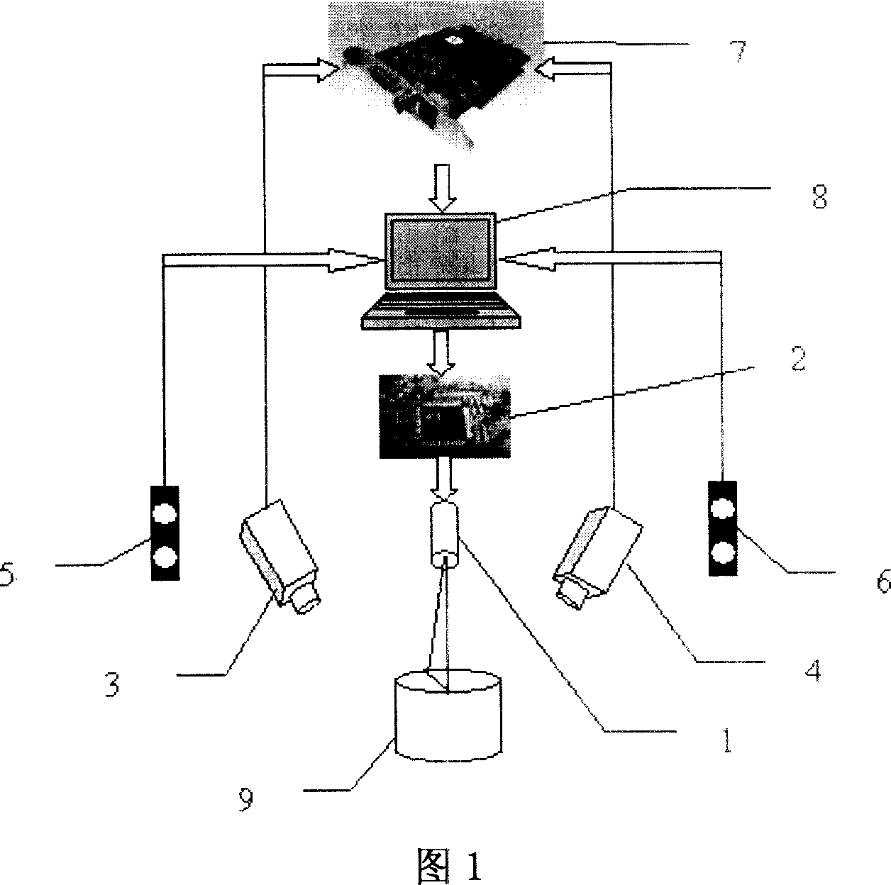
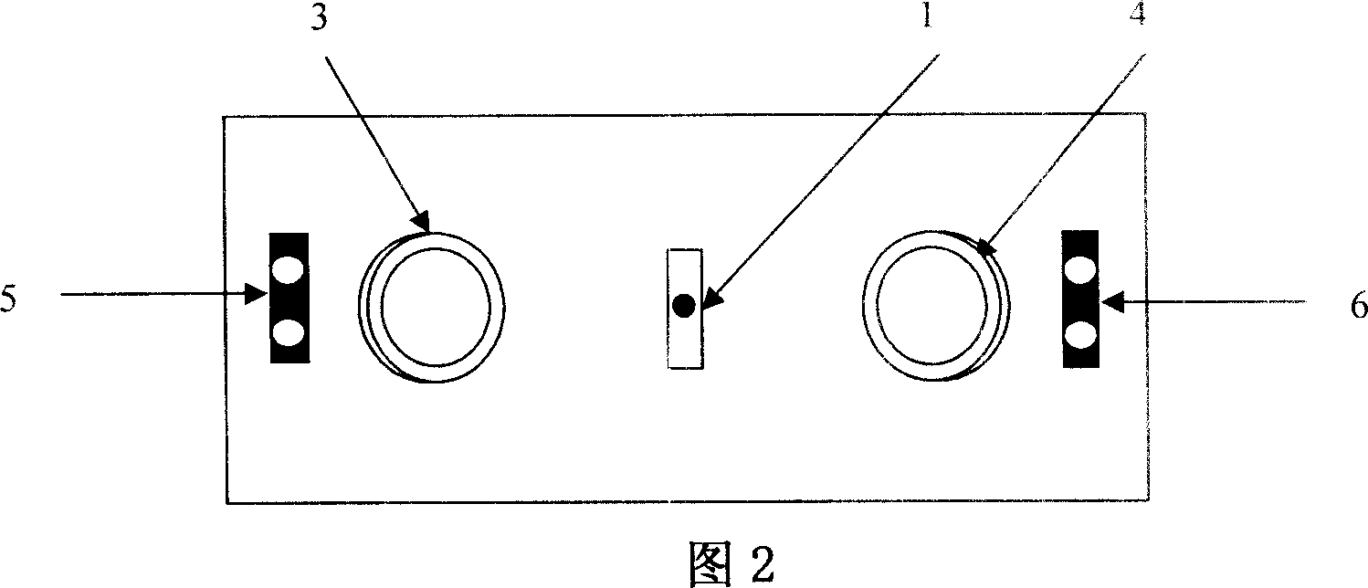
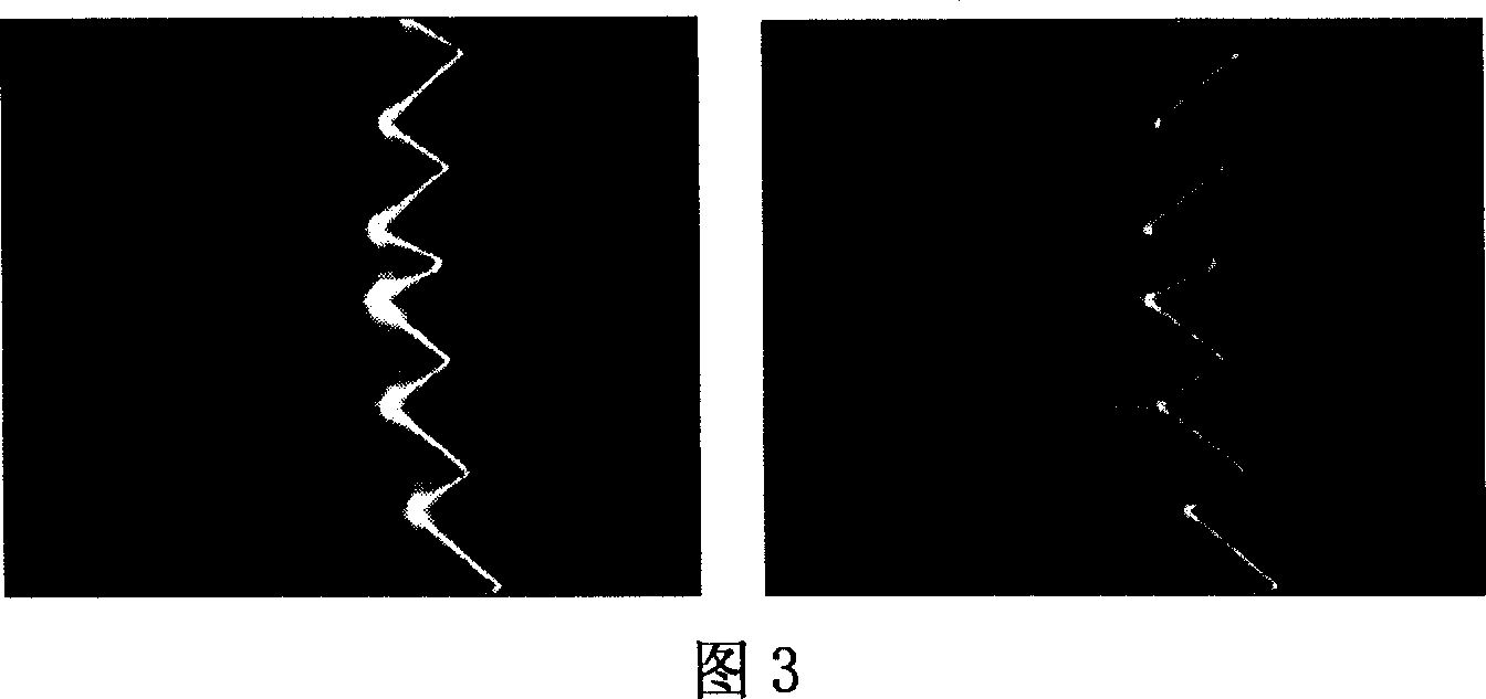
[0031] The semiconductor laser 1 uses a 650nm He-Ne laser module and a cylindrical mirror to produce a 0.1mm wide light strip projected onto the surface of the workpiece to be tested. The CCD camera 3 and CCD camera 4 form a certain angle with the laser and shoot within a certain range. The laser light stripe pattern is transmitted to the computer 8 through the image acquisition card 7, and the computer extracts the light stripe information through the corresponding image processing method, and determines the modulation amount of the laser intensity by detecting the width and continuity of the light stripe, and then through the laser intensity The control circuit 2 adjusts the light intensity. At the same time, the collision avoidance sensor 5 and the collision avoidance sensor 6 detect the distance between the probe and the workpiece 9 in real time to avoid collision between the probe and the workpiece.


PUM


Abstract

The invention relates to dynamic three-dimensional laser scanning gauge head. It is made up of semiconductor laser, laser intensity control circuit, CCD video camera, image collecting card, computer, collision avoidance sensor group. It uses double pick-up heads information matching to avoid scanning blind, gain whole work-piece interface information, adjusts laser intensity to collect data for work-piece surface with different material to avoid work-piece material limitation, uses collision avoidance to ensure the gauge head safety while dynamic scanning, make it can scan any way in space to accomplish the work-piece whole data collection. It is suited for on line detecting in dynamic environment, has great practicability and generalization potential.

Description

technical field [0001] The invention belongs to the field of advanced measurement and detection technology Background technique [0002] Today, with the rapid development of computers, three-dimensional geometric modeling technology has been widely used by the manufacturing industry in various aspects such as tool and mold design, program review, automatic processing and manufacturing, and management and maintenance. And often we will encounter such a problem, that is, the customer only gives you a physical sample or hand pull model, without drawing CAD data files, engineers cannot get accurate dimensions, and it is even more difficult to manufacture molds. The traditional engraving method takes a long time and the effect is not good. At this time, we need to use various measurement methods and three-dimensional geometric modeling methods to convert the original object into a three-dimensional digital model on the computer. [0003] Three-dimensional scanning is a high-tech...

Claims


Application Information

Patent Timeline
Patent Type & Authority Applications(China)
IPC IPC(8): G01B11/00G01B11/03G01B21/00G01B21/04G06F3/00
Inventor 马孜胡英黄进林娜赵骥
Owner DALIAN MARITIME UNIVERSITY
Why Eureka
Try Eureka