Designing method of reinforced concrete large space slope roof
A technology of reinforced concrete and design methods, which is applied to roofs, building components, buildings, etc., to achieve the effect of shortening the roof construction period and saving investment
- Summary
- Abstract
- Description
- Claims
- Application Information
AI Technical Summary
Problems solved by technology
Method used
Image


Examples
Embodiment 1
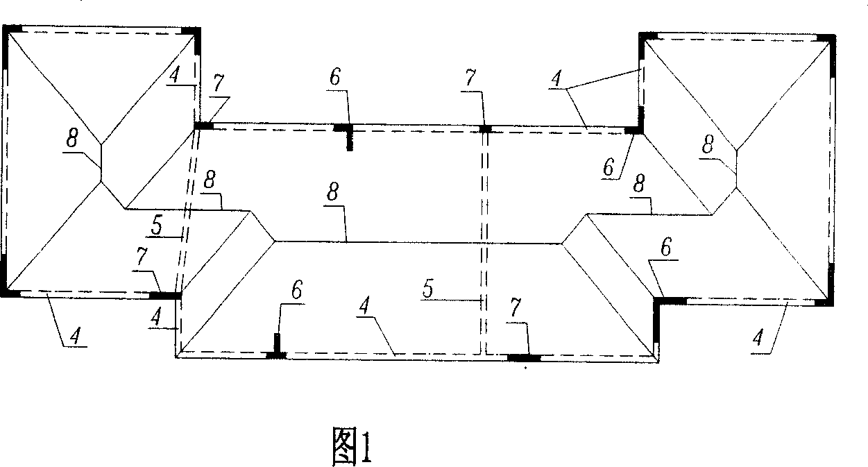
[0059] As shown in Figure 8, the original roof design was modified by experiment: it includes the overall layout of the following structural components: the eaves side beams are supported on the concrete columns at the eaves; the sloping roof panels of each section are from the eaves to the mid-span at an inclination angle of 30 degrees Elevated and tilted, its bottom is supported on the eave edge beams; the sloping roof panels of each section are connected to each other in the middle of the span to form a roof ridge; in order to better realize the large space, the resistance of the eave edge beams at the corners is fully utilized. Tensile force; in the middle is the partition wall of the house, so a tension beam is set up, which can be hidden in the wall; the rest is arranged at a certain distance from the horizontal push-resisting member, that is, the special-shaped concrete column, and the "L"-shaped vertical eaves side beam wall The limb section is 0.20 meters wide and 0.60...
Embodiment 2
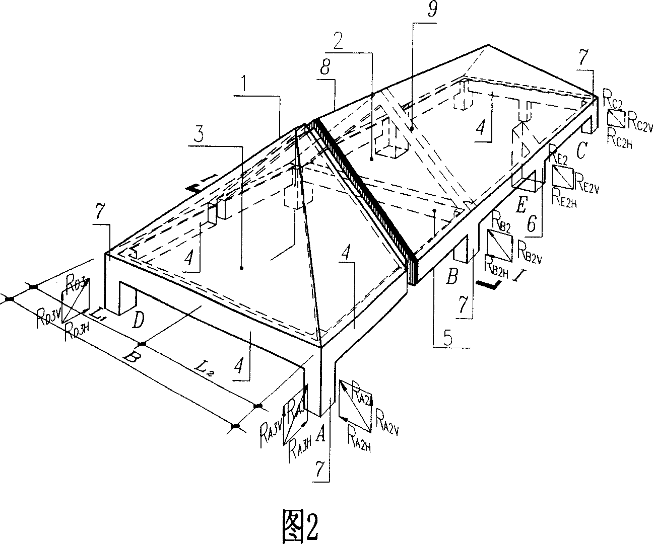
[0061] As shown in Figure 9-11, the experimental modification-the original roof design: it includes the overall layout of the following structural components: the eaves side beams are supported on the concrete columns at the eaves; Elevated at 45 degrees and placed obliquely, its bottom is supported on the eave side beams; the sloping roof panels of each section are connected to each other in the middle of the span to form a roof ridge; in order to better realize the large space, the eave side beams at the corners are fully utilized There is no tensile beam in the middle, and only horizontal push-resistant components, namely concrete special-shaped columns, are arranged. The wall section of the "T"-shaped vertical eaves side beam is 0.20 meters wide and 0.60 meters long, and the wall protruding 0.20 meters thick is 0.40 meters. rice. This example includes dormer windows 10 and overhanging eaves 11, and the structure is relatively complicated, so the analysis and calculation ar...
Embodiment 3
[0063] As shown in Figure 12, the original roof design was tested and modified: it includes the overall layout of the following structural components: the eaves side beams are supported on the concrete columns at the eaves; the sloping roof panels of each section are at an angle of 26 degrees from the eaves to the mid-span Elevated and tilted, its bottom is supported on the eave edge beams; the sloping roof panels of each section are connected to each other in the middle of the span to form a roof ridge; in order to better realize the large space, the resistance of the eave edge beams at the corners is fully utilized. Tension force, without tension beams in the middle, arrange nine horizontal push-resisting members, that is, concrete special-shaped columns, "L" and "T" shaped vertical eaves side beams, the wall section is 0.20 meters wide, 0.70 meters long, protruding 0.20 meters thick Wall surface 0.50 meters, all the other items are with embodiment 2. Adopting this scheme sh...
PUM
 Abstract
Description
Claims
Application Information
 - R&D
- Intellectual Property
- Life Sciences
- Materials
- Tech Scout
- Unparalleled Data Quality
- Higher Quality Content
- 60% Fewer Hallucinations
Browse by: Latest US Patents, China's latest patents, Technical Efficacy Thesaurus, Application Domain, Technology Topic, Popular Technical Reports.
© 2025 PatSnap. All rights reserved.Legal|Privacy policy|Modern Slavery Act Transparency Statement|Sitemap|About US| Contact US: help@patsnap.com