Arrangement of cable for fan

A cable and fan technology, which is applied in the field of fan cable arrangement and structure, can solve the problems of inconvenient and troublesome cable storage, the space occupied by the frame body 111, and the lack of wide application of the fan 11, etc.

Inactive Publication Date: 2007-04-04
ASIA VITAL COMPONENTS SHENZHEN CO LTD
View PDF0 Cites 5 Cited by
  • Summary
  • Abstract
  • Description
  • Claims
  • Application Information

AI Technical Summary

Problems solved by technology

[0004] Please refer to Fig. 1 again, as shown in the figure, this figure is a partial section of Fig. 2 to present a frame that generally does not have the function of accommodating cables, and the cables 111d of this frame 111 can only be wrapped around here The middle section 111g of the frame body 111, but because the middle section 111g is arranged in alignment with the radial direction of the frame body 111, when the cables are wrapped and stored, the cables will protrude out of the frame body 111, which is easy to cause the cables to protrude Cause interference or obstruction, causing inconvenience and troubles in cable storage, and Figure 1 does not have the design of the receiving part 111f shown on the frame body 111 in Figure 2, which makes it impossible to position the connector 111e and cause the cable to fall off The situation is very inconvenient, so in order to make this frame body 111 have the function of completely accommodating the cable 111d and storing and positioning, the structure of the frame body 111 as shown in Figure 2 is formed, but when the fan 11 of this prior art is assembled on When it is on the heat sink, it must be assembled in a specific direction or position so that the connector 111e can achieve the purpose of connection. Therefore, the fan 11 in the prior art is not widely applicable, and it must be remade in order to meet the demand. Frame mold (mold of frame), so this kind of fan 11 in the prior art that is easily limited by the assembly method of the fan not only causes inconvenience for users to assemble, but also reduces the added value of the fan 11 due to low compatibility
[0005] And the frame body 111 adds an opening 111b for the purpose of arranging the connector 111e, which not only makes the cost of making the frame body mold higher than that of the general frame body mold, but also makes the frame body 111 take up a lot of space, and The processing technology added when the frame body 111 is processing the opening 111b is not only too cumbersome, but even affects the production capacity
[0006] In addition, the opening 111b of the frame body 111 must be provided with a cover plate 111a, which not only makes the fan 11 take longer to process than ordinary fans when it is assembled into a finished product, but also makes the fan 11 run due to insufficient structure. solid but noisy

Method used


Image

  • Arrangement of cable for fan
  • Arrangement of cable for fan
  • Arrangement of cable for fan

Examples


Embodiment Construction

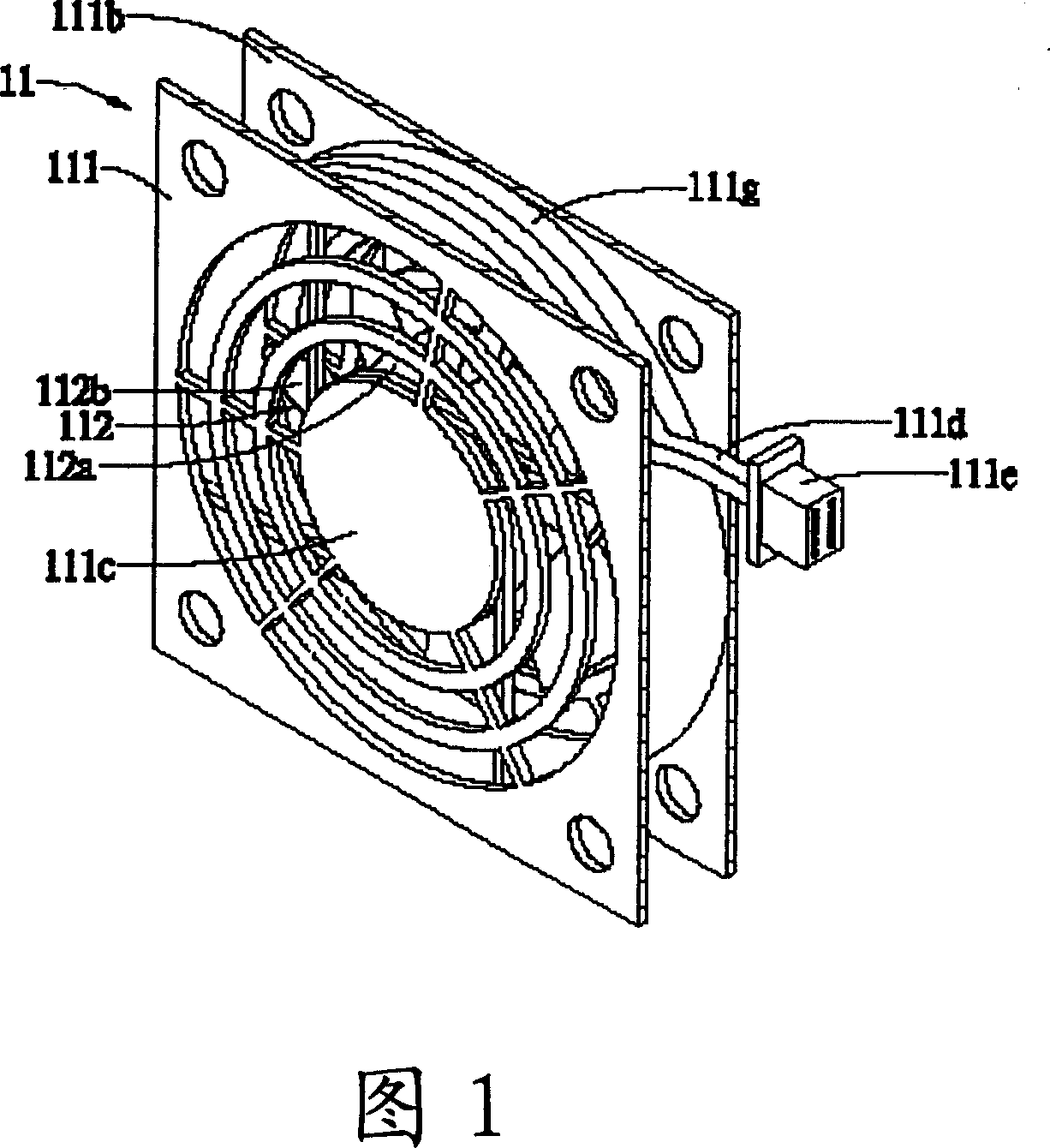
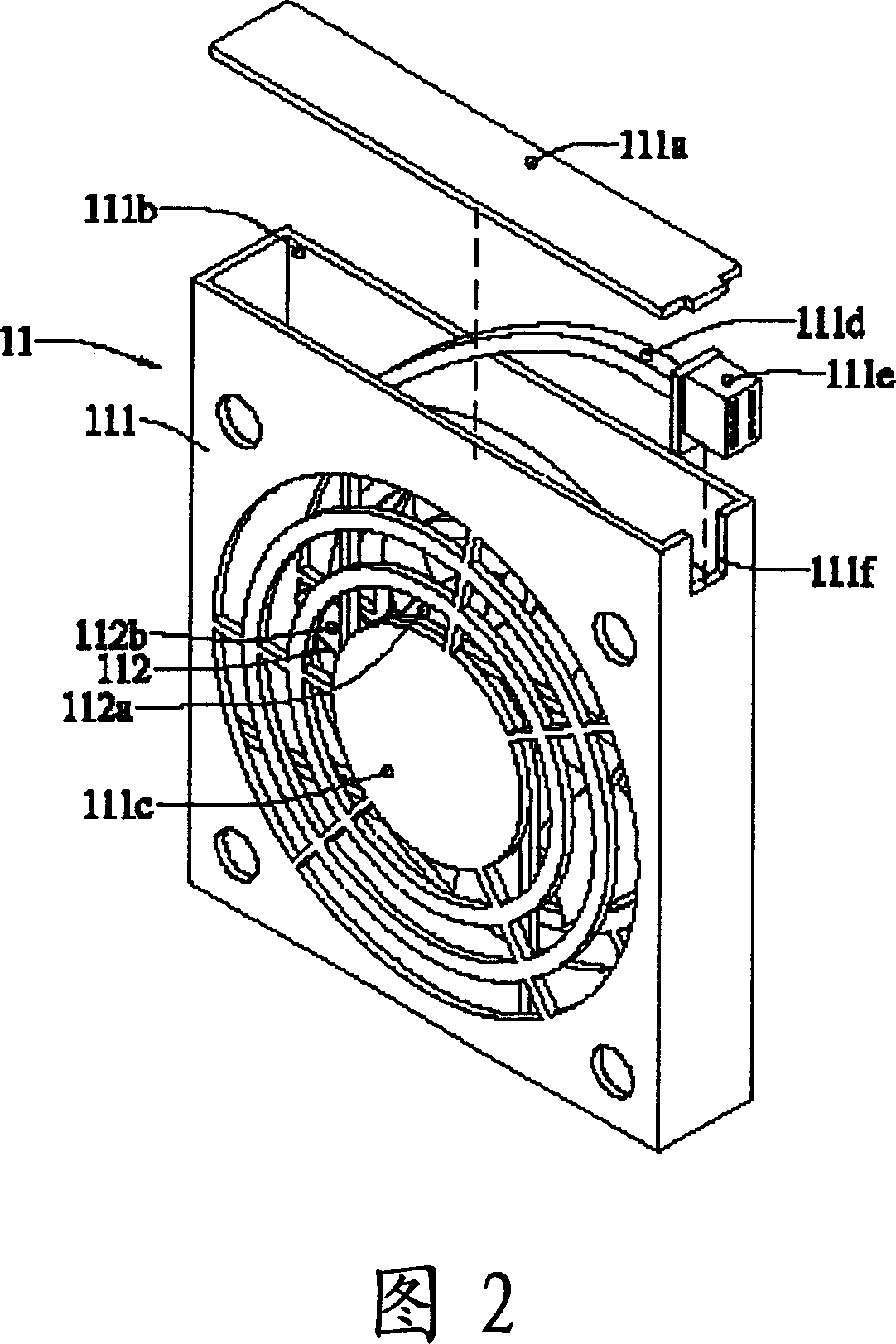
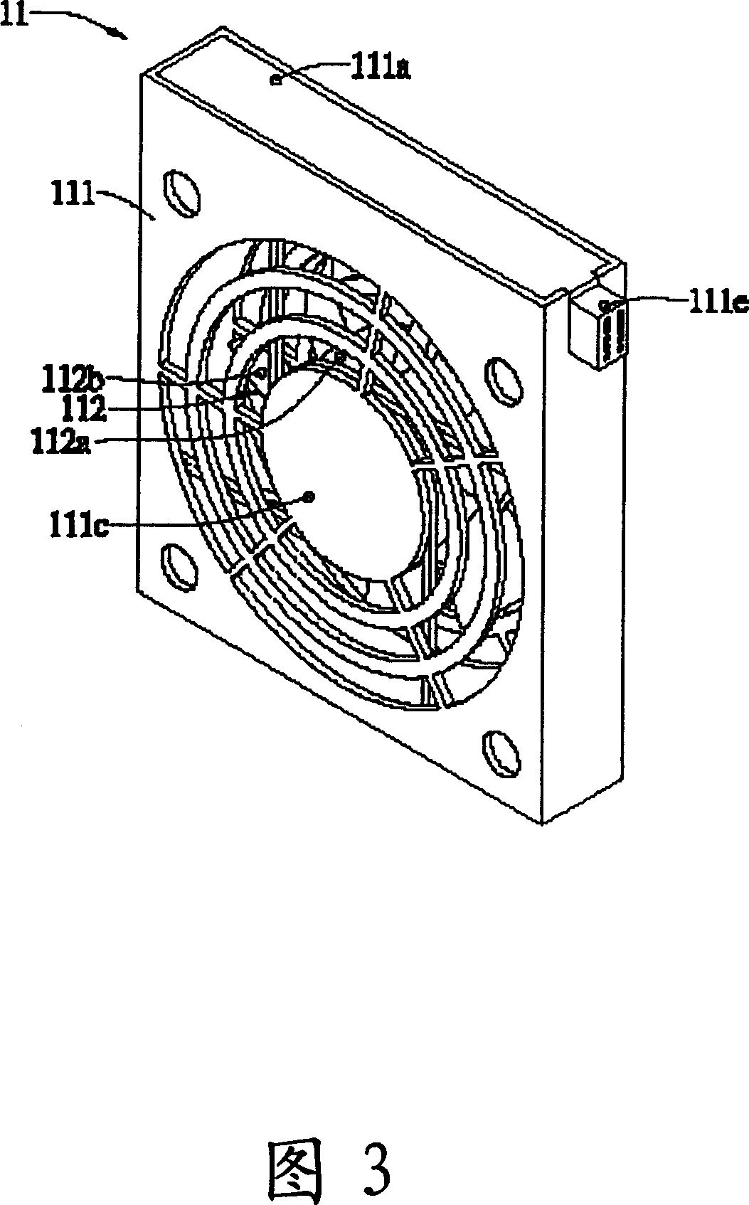
[0023] The present invention provides a fan cable arrangement structure, please refer to Figure 4, which is a preferred embodiment of the present invention, as shown in the figure, the fan 21 includes a frame body 211 and a fan blade part 212, wherein the fan blade part 212 It is composed of a fan hub 212a and fan blades 212b which are arranged around the fan hub 212a; and the frame body 211 is provided with a driving part 211c which can be pivotally connected to the fan hub 212a of the fan blade part 212, and the driving part 211c is connected to A cable 211d is provided, and a connector 211e is provided at the end of the cable 211d.

[0024] The frame body 211 is provided with a middle section 211f, and the middle section 211f is provided with a groove 211g for setting the cable 211d, and the groove 211g is provided with a stopper 211h.

[0025] Please refer to Fig. 4 and Fig. 5 again, as shown in the figure, when accommodating the cable 211d, only the cable 211d connected t...


PUM


Abstract

A fan cable yarn arranging structure is mainly made up of a frame body and a fan blade part. The frame body has a drive part and a mid-section part opened a groove on it. The fan blade part consists of a fan hub and fan blades around the hub. In the drive part of the frame body is set a fan hub and is connected the cable yarn. At the end of the cable yarn is disposed a connector. When taking in the cable yarn, it needs only to connect the cable yarn in the drive part into the groove of the mid-section part.

Description

technical field [0001] The invention relates to a fan cable arrangement structure, in particular to a fan cable arrangement structure for positioning the cables. Background technique [0002] Please refer to FIG. 1 and FIG. 2, which are a perspective view of a partial cross-section of a fan in the prior art and an exploded view of a fan in the prior art. As shown in the figure: the fan 11 includes a frame body 111 and a blade portion 112, wherein the blade Part 112 is made up of fan hub 112a and fan blades 112b which are arranged around fan hub 112a; 111c is connected with a cable 111d, the cable 111d extends through the inside of the frame 111 to the opening 111b provided on one side of the frame 111, the end of the cable 111d is provided with a connector 111e, and The opening 111b is provided with a receiving portion 111f for the connector 111e. [0003] Please refer to Fig. 1, Fig. 2 and Fig. 3 again, as shown in the figure, when assembling, the fan blade part 112 is pi...

Claims


Application Information

Patent Timeline
Patent Type & Authority Applications(China)
IPC IPC(8): F04D29/00H05K7/02
Inventor 游守德
Owner ASIA VITAL COMPONENTS SHENZHEN CO LTD
Why Eureka
Try Eureka