Medical leading wire and manufacture thereof

A technology of guiding wires and core wires, applied in the direction of guiding wires, catheters, etc., to reduce the burden and reduce the effect of invasion

Inactive Publication Date: 2007-04-04
ASAHI INTECC CO LTD
View PDF2 Cites 18 Cited by
  • Summary
  • Abstract
  • Description
  • Claims
  • Application Information

AI Technical Summary

Problems solved by technology

[0006] In the related art of record, none of the guidewires attempt to effectively utilize the buoyancy forces generated in the blood flow and thereby ensure good maneuverability of the guidewire as it is advanced through the vessel

Method used


Image

  • Medical leading wire and manufacture thereof
  • Medical leading wire and manufacture thereof
  • Medical leading wire and manufacture thereof

Examples


Embodiment Construction

[0063] In the following detailed description of the embodiments, the same reference numerals are used for the same kind of structural features.

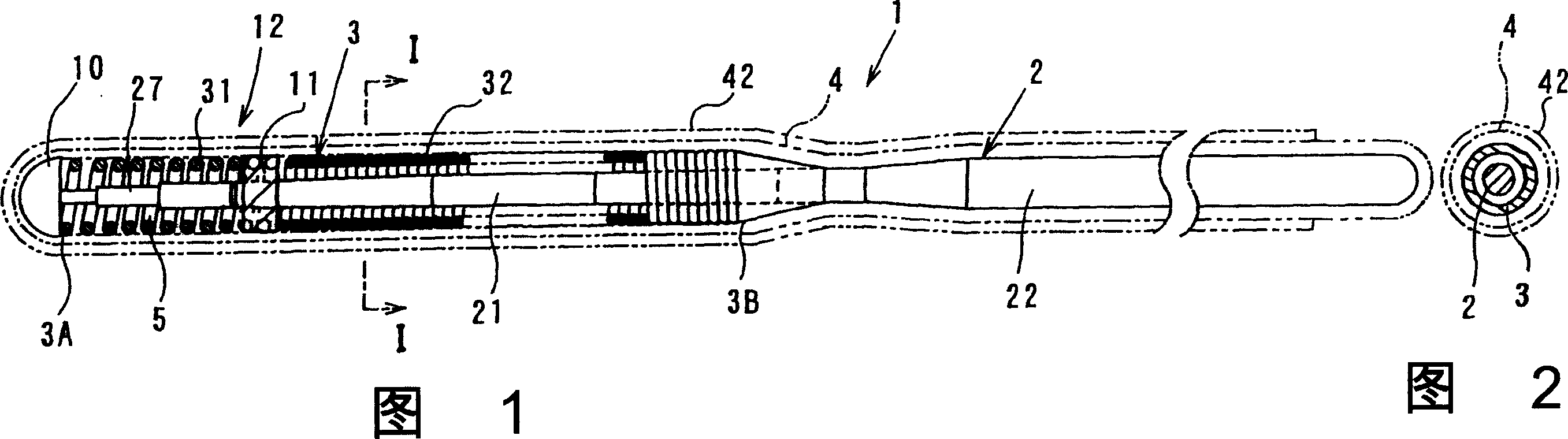
[0064] Referring to FIGS. 1 to 4, there is shown a medical guide wire 1 according to a first embodiment of the present invention. The medical guide wire 1 (hereinafter simply referred to as "guide wire 1") has an elongated core wire 2 and is sheathed in a thin A helical spring 3 on the outer surface of the distal portion 21 of the long core wire 2 . The elongated core wire 2 is made of stainless steel wire and its distal portion 21 is about 300 mm in length, while the remaining guide wire 1 acts as a proximal portion 22 extending in length by about 1200 mm or about 2700 mm.

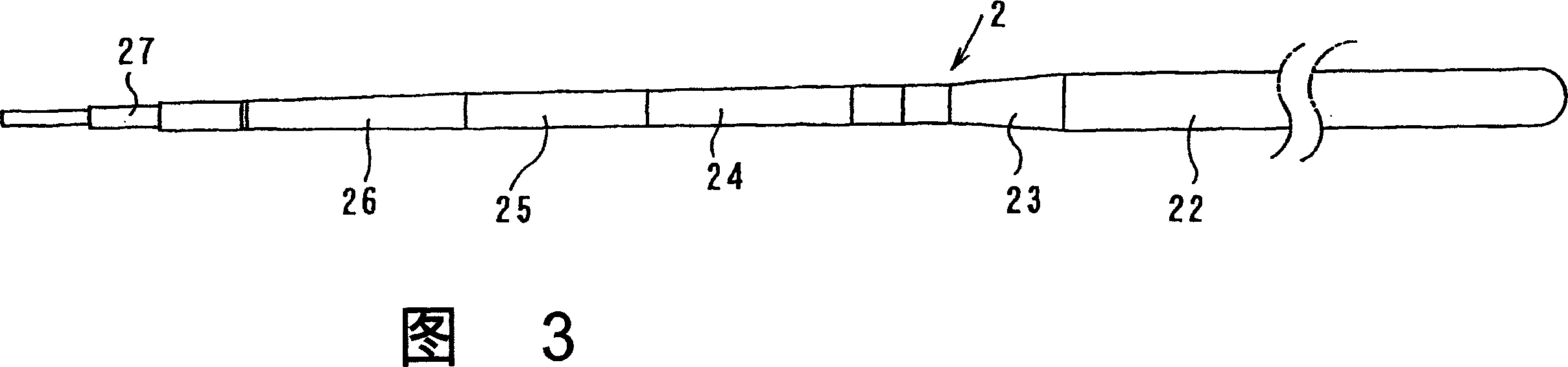
[0065] The distal portion 21 has a large tapered portion 23 of a taper, a small tapered portion 24 of a taper, a cylindrical portion 25, a small tapered portion 26 of a taper and a multi-step flat portion 27 (for example, from the far The thickness from the end...


PUM


Abstract

A medical leading line features that a spiral spring has a ray shielding part on its front spiral Bourdon tube, a slender line has a fine far end in said spiral spring and a thick near end, said far end of spiral spring and said slender line are tightly fixed for making the external surface of spiral spring to be covered by a coated layer, and a floating chamber is arranged in said ray shielding part for providing a floating force to said far end to make it to be vertically suspended in blood.

Description

technical field [0001] The present invention relates to a medical guide wire and a method of manufacturing the same, the guide wire has improved maneuverability so as to effectively utilize blood flow to travel deeply into a lumen system. Background technique [0002] When carrying out treatment, before using the catheter, it is necessary to first insert a medical guide wire (hereinafter simply referred to as "guide wire") into the blood vessel as a guide for the catheter. Various inventions have been made in order to allow guide wires to reach desired regions of the intricately sinuous parts of the vasculature. [0003] By way of illustration, Japanese Published Patent Application 2000-135289 discloses a guidewire in which a radiopaque coiled spring steel wire is attached to a distal end of an elongated core wire, the coiled spring steel wire is covered with an artificial tube . The outer surface of the helical spring wire is covered with a hydrophilic polymer to ensure s...

Claims


Application Information

Patent Timeline
Patent Type & Authority Applications(China)
IPC IPC(8): A61M25/01A61M25/09
Inventor 加藤富久
Owner ASAHI INTECC CO LTD
Why Eureka
Try Eureka