Method for realizing optical point joint seal in optical-fiber close-packed array
A technology of line array and optical fiber, which is applied in the field of close connection of light spots in optical fiber dense line array, can solve the problems of complex control circuit, achieve the effect of improving accuracy, reducing positional accuracy, and increasing focal depth
- Summary
- Abstract
- Description
- Claims
- Application Information
AI Technical Summary
Problems solved by technology
Method used
Image
Examples
Embodiment 1
[0032] 1) Strip off the coating layer of the single-mode optical fiber;
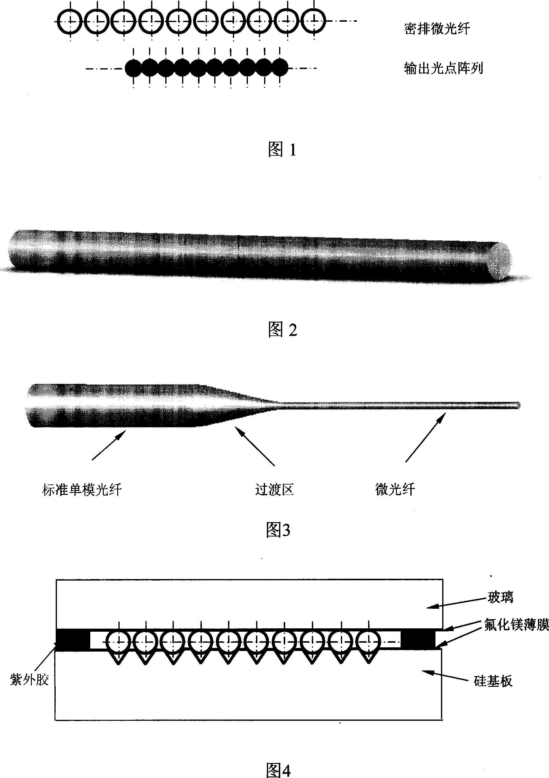
[0033] 2) The high-power laser is condensed onto the optical fiber through a focusing lens, the heat generated by the laser melts the optical fiber, and a micro-optical fiber with a diameter of 20 microns is obtained by drawing the optical fiber;
[0034] 3) V-shaped grooves with a pitch of 24 microns are etched in parallel on the silicon wafer, and a layer of magnesium fluoride film with a thickness of 0.3-1 micron is plated on the surface of the silicon wafer where the V-shaped grooves are etched; The fiber ends are arranged in parallel and horizontally in the V-shaped groove on the silicon wafer, and then a glass sheet coated with a 0.3-1 micron film on the surface of the micro-fiber array is covered, and the glass sheet and the silicon wafer are fixed by UV glue, as shown in Figure 4. Show.
[0035] 4) Fix the silicon wafer and the standard optical fiber near the transition zone to the base with ultravio...
Embodiment 2
[0038] 1) Strip off the coating layer of the single-mode fiber;
[0039] 2) The high-power laser is condensed onto the optical fiber through a focusing lens, the heat generated by the laser melts the optical fiber, and a micro-optical fiber with a diameter of 10 microns is obtained by drawing the optical fiber;
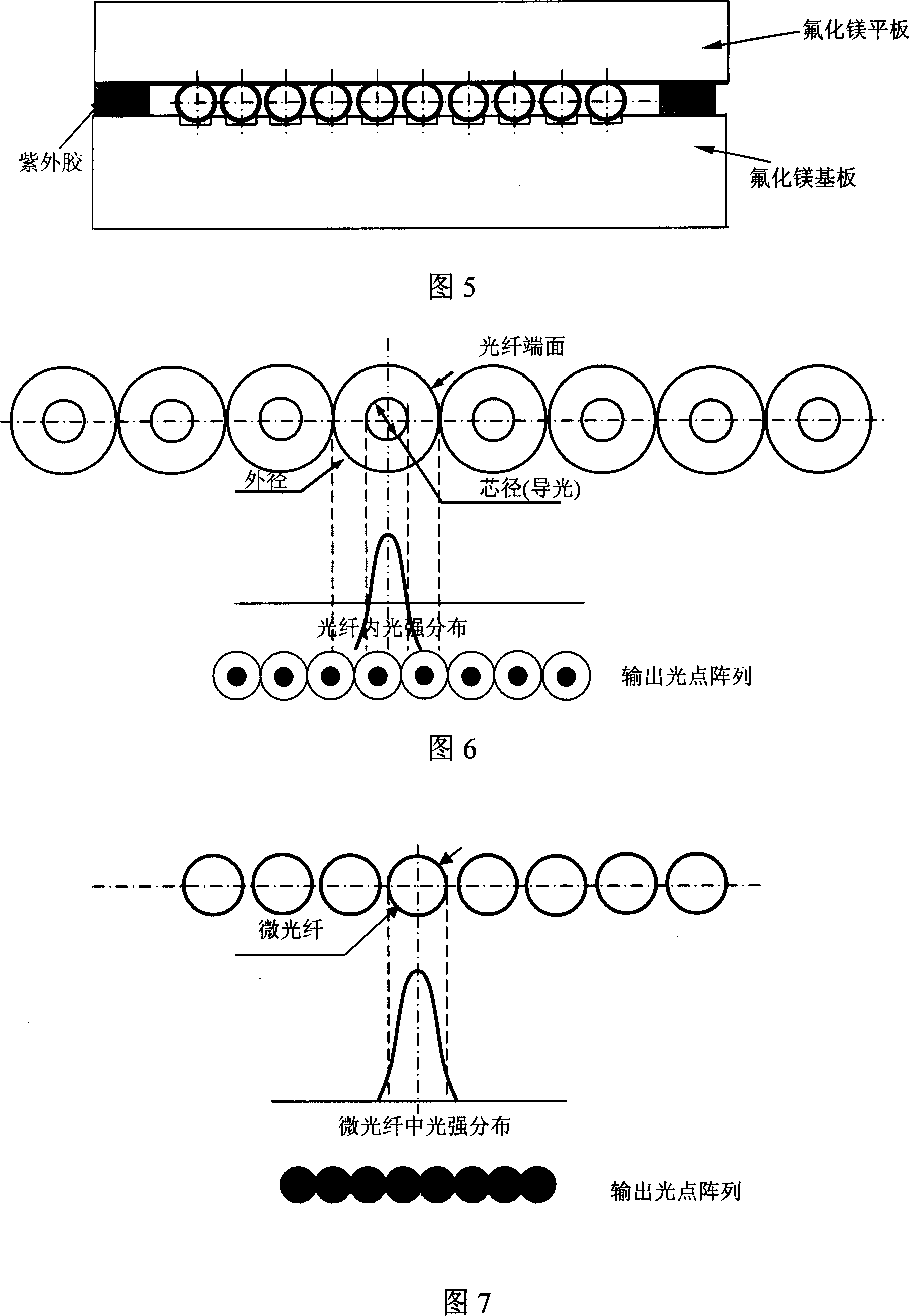
[0040] 3) On the magnesium fluoride substrate, parallel grooves with an adjacent interval of 13 microns, a width of 8 microns, and a depth of 5 microns are etched on the magnesium fluoride substrate by photolithography and plasma beams, and the micro-fibers are arranged horizontally in parallel in the parallel grooves on the substrate. A magnesium fluoride sheet is covered on the micro-fiber array, and the magnesium fluoride sheet and the substrate are fixed by ultraviolet glue, as shown in Figure 5.
[0041] 4) Fix the magnesium fluoride substrate and the standard optical fiber near the transition zone to the base with ultraviolet glue, and connect the FC interface conne...
PUM
 Abstract
Description
Claims
Application Information
 - R&D
- Intellectual Property
- Life Sciences
- Materials
- Tech Scout
- Unparalleled Data Quality
- Higher Quality Content
- 60% Fewer Hallucinations
Browse by: Latest US Patents, China's latest patents, Technical Efficacy Thesaurus, Application Domain, Technology Topic, Popular Technical Reports.
© 2025 PatSnap. All rights reserved.Legal|Privacy policy|Modern Slavery Act Transparency Statement|Sitemap|About US| Contact US: help@patsnap.com


