
Rolling rounder for rolling steel bar

A chamfering and rolling technology, which is applied in the field of steel bar chamfering and rolling full circle devices, can solve problems such as waste products, large deformation of steel bar joints, quality and strength of steel wire heads, etc.

Inactive Publication Date: 2007-03-21
孙永林
View PDF0 Cites 5 Cited by
  • Summary
  • Abstract
  • Description
  • Claims
  • Application Information

AI Technical Summary

Problems solved by technology

[0003] All there is following defective in above two ways: 1, the end of the straight thread thread head of the steel bar that processes often has burr, and this burr can bring following problem: the one, may be screwed in the connection sleeve when screwing into the straight thread connection sleeve. The threaded buckle is bumped, which is not easy to screw in and even causes damage to the threaded buckle, resulting in waste products; the second is the burr at the end of the straight thread thread head, which will cause a gap between the butt end faces of the two steel bars after the butt joint, and the contact surface is small, so that when the pressure is applied , the deformation of the steel joint will be large, and the connection quality is not high
2. The cross-section of the steel bar to be processed is usually not a standard circle, there is out-of-roundness, and there are raised ribs on the surface. Therefore, if the direct rolling method is used, the quality of the processed wire head is difficult to guarantee. Although the rib stripping and rolling method first cuts off the ribs on the surface of the steel bar, because of the cutting process, it will affect the quality and strength of the steel wire head with a small diameter, so that the performance of the final connection joint is not high.

Method used


Image

  • Rolling rounder for rolling steel bar
  • Rolling rounder for rolling steel bar
  • Rolling rounder for rolling steel bar

Examples


Embodiment

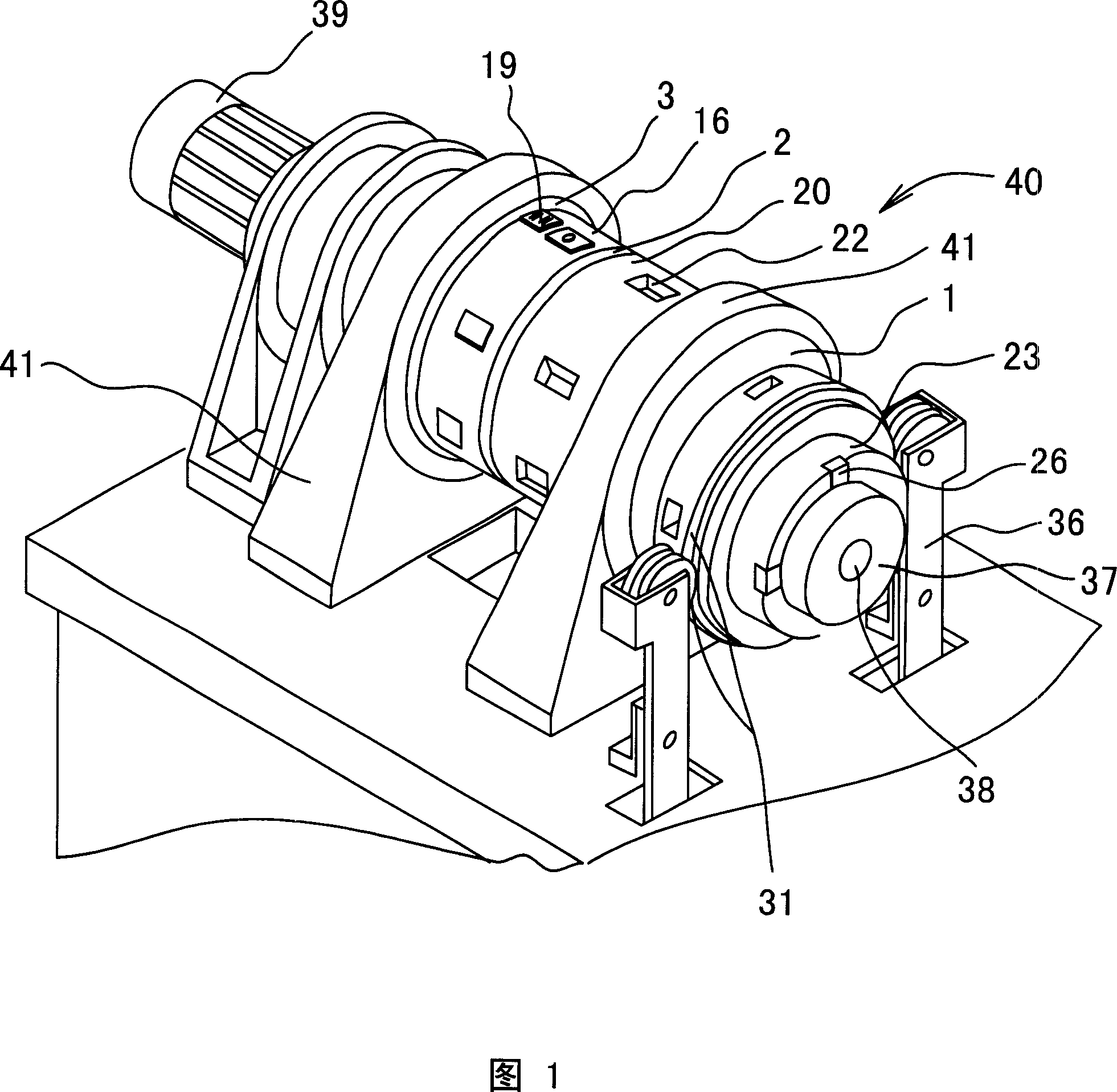
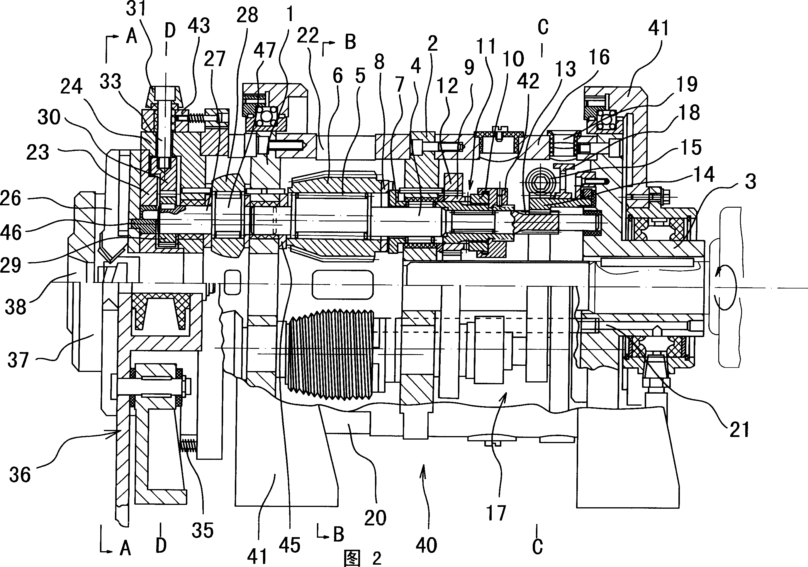
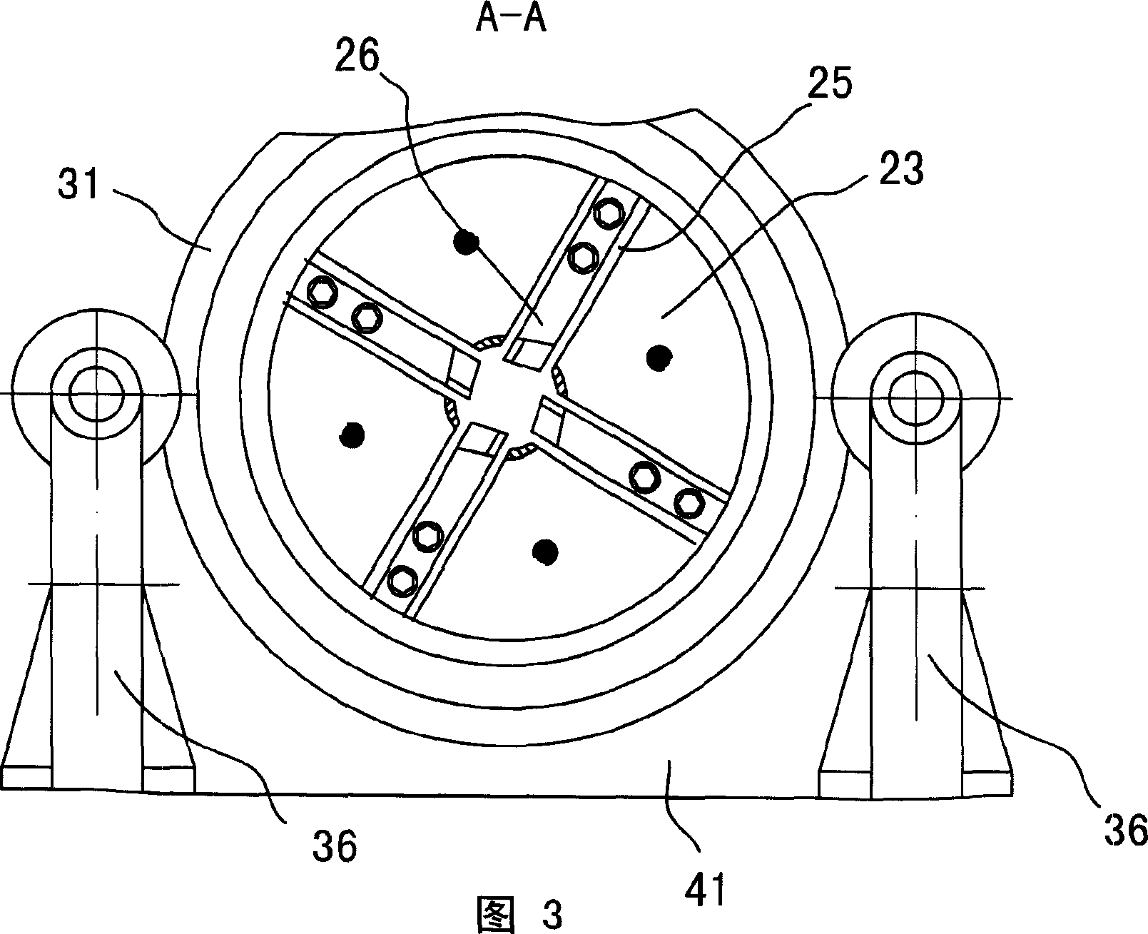
[0029] Embodiment: See accompanying drawing 2, accompanying drawing 4 and accompanying drawing 9, a kind of helical tooth rolling steel wire end equipment, the chamfering and rounding device that the present invention relates to at the front part and the helical tooth rolling at the rear side The supporting connection of the steel wire head device is formed.

[0030] Referring to accompanying drawings 2, 3, 6 and 9, the specific structure of the chamfering and rounding mechanism is as follows: it includes four chamfering and rounding mechanisms uniformly distributed in the circumferential direction around the central axis of rolling rotation. Circular eccentric shaft 27, each chamfered full-circle eccentric shaft 27 is composed of at least a chamfered eccentric section 46 at the front, a central main shaft section and a rear full-circle eccentric section 47 in the axial direction, wherein the chamfered eccentric section 46 The eccentric phase difference with the full circle ec...


PUM


Abstract

The steel bar end chamfering and rounding roller includes at least three eccentric chamfering and rounding shafts, each of which consists of an eccentric chamfering section, a main shaft section and an eccentric rounding section. The eccentric chamfering section and the eccentric rounding section has eccentric phase difference of 90-180 deg; the eccentric rounding section is provided with rounding wheel; the eccentric chamfering section is provided with corresponding chamfering cutter; and the main shaft section is provided with outer gears meshed to the same inner gear sleeve. There are also dialing disc, locating part, locating ring with locating notch and spring, and the locating part and the locating notch are fitted in different phases corresponding to three states, including chamfering, rounding and free position. The present invention is used in chamfering and rounding steel bar before rolling for raised final steel bar quality.

Description

technical field [0001] The invention relates to processing equipment for connecting wire heads of steel bars in the construction industry, in particular to a steel bar chamfering rolling and rounding device. The front-stage process of the steel wire head, in order to finally improve the quality of the steel wire head. Background technique [0002] At present, the mechanical connection of steel bars in the construction industry is the main trend, and the direct rolling straight thread mechanical connection and the stripping rib rolling straight thread mechanical connection are the dominant trends. Among them, the direct rolling straight thread mechanical connection is to directly roll out the straight thread thread head with the rolling thread head device at the end of the steel bar, and then connect the steel bars with the straight thread connecting sleeve. The stripping rib rolling straight thread mechanical connection is to first cut off the ribs on the end surface of the...

Claims


Application Information

Patent Timeline
IPC IPC(8): B23P23/02B23B5/16B21F21/00B21H3/04B21F99/00
Inventor 孙永林
Owner 孙永林
Learn More