Stator for annular generator

A stator and ring-shaped technology, applied in the direction of magnetic circuit shape/style/structure, winding insulation shape/style/structure, winding conductor shape/style/structure, etc., can solve problems such as influence and prolongation of time

Inactive Publication Date: 2007-03-07
LG ELECTRONICS (TIANJIN) APPLIANCES CO LTD
View PDF0 Cites 11 Cited by
  • Summary
  • Abstract
  • Description
  • Claims
  • Application Information

AI Technical Summary

Problems solved by technology

Therefore, the above-mentioned welding operation leads to prolongation of the time required for the joining operation, and at the same time, the heat generated in the above-mentioned welding operation adversely affects the above-mentioned divided stator cores 111.

Method used


Image

  • Stator for annular generator
  • Stator for annular generator
  • Stator for annular generator

Examples


Embodiment Construction

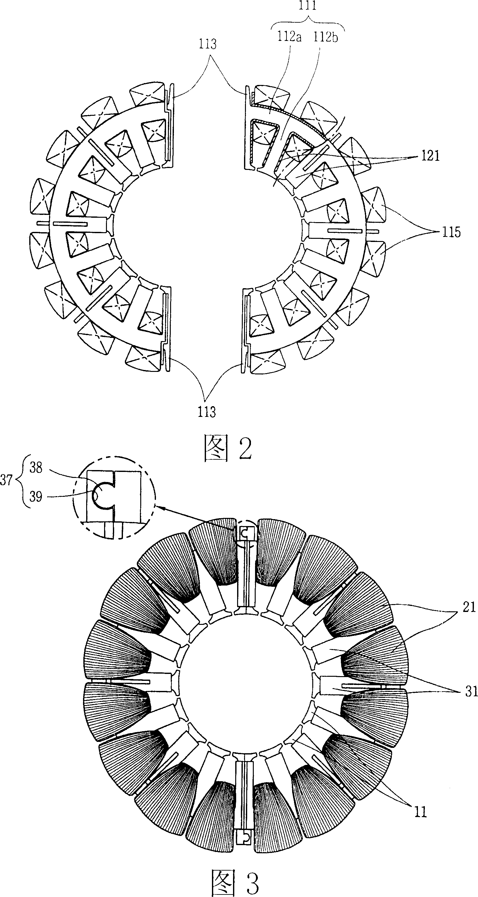
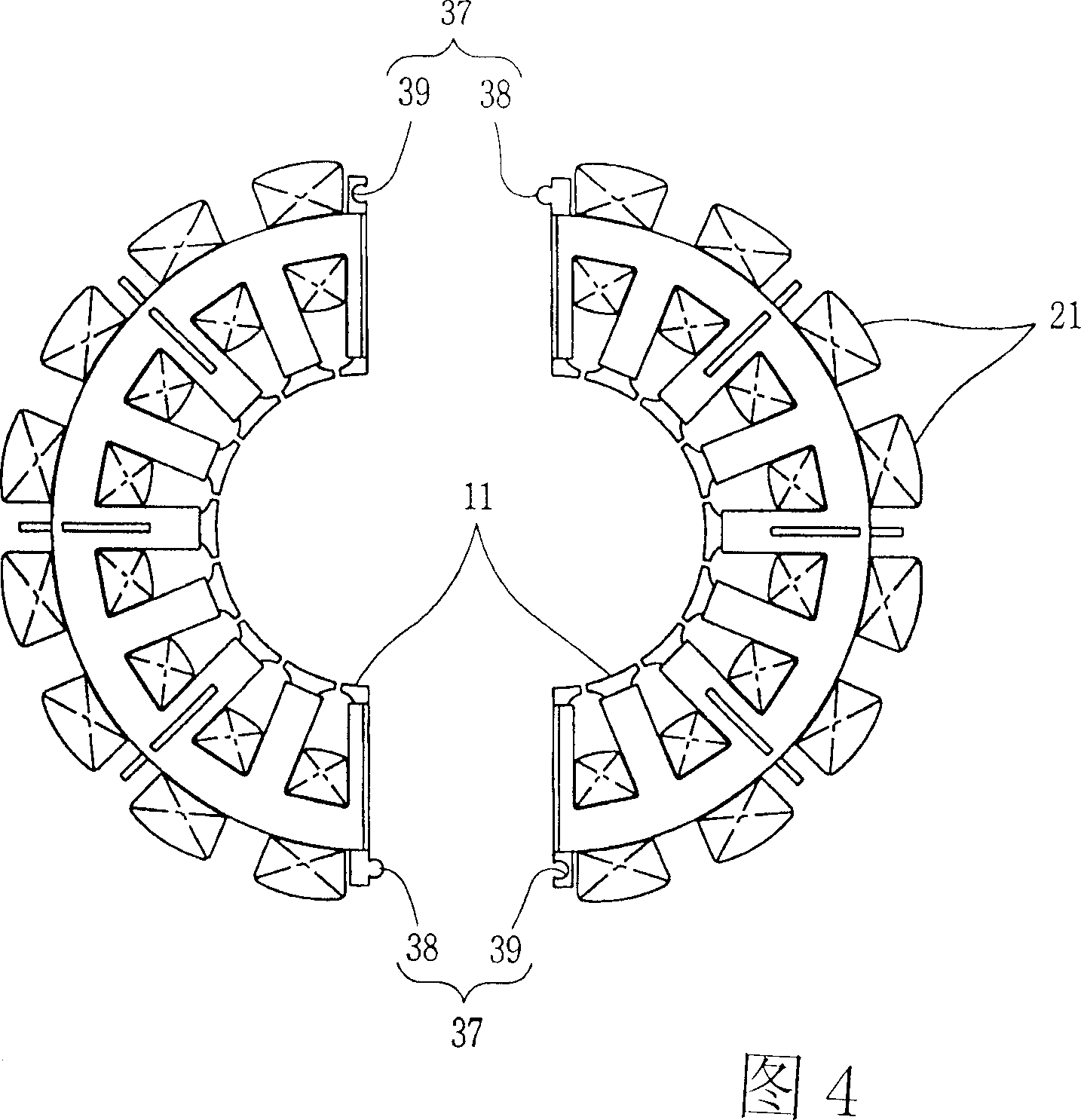
[0027] As shown in Figures 3 to 7, the stator of the ring motor in the present invention includes the following parts: an arc-shaped yoke portion 12a is provided, and protrudes toward the above-mentioned yoke portion 12a along the radial direction, and a predetermined distance along the peripheral direction to form a plurality of tooth portions 12b of slots 12c therebetween, and a plurality of split stator cores 11 combined with each other in order to form a ring shape; on the periphery of the above-mentioned yoke portion 12a The wound stator coil 21; a plurality of insulating members 31 that accommodate the yoke portion 12a and the tooth portion 12b inside and insulate the yoke portion 12a, the tooth portion 12b and the stator coil 21 from each other; One of the adjacent insulating members 31 is protrudingly provided with a coupling protrusion 38 toward the other, and the other of the mutually adjacent insulating members 31 is provided with a protrusion receiving portion 39 co...


PUM


Abstract

This ring motor stator, which comprises the following parts: magnetic yoke part with arc shape and its protruding part along radium direction and several gear parts to form plug tank between with certain distance to form several cutting stator iron chip; stator coil outside magnetic yoke; several insulation iron chip of the magnetic yoke parts and gear parts and stator iron chip; protruding part set relative to the binding place near to the insulation; one integration part to integrate insulation parts and stator iron chips.

Description

technical field [0001] The invention relates to a stator of an annular electric machine. Background technique [0002] As shown in Fig. 1 and Fig. 2, the stator of the ring-shaped motor in the prior art includes the following parts: a split stator core 111 that is combined with each other to form a ring-shaped semicircular shape; The stator coil 115 of the core 111; the insulating member 121 which houses the divided stator core 111 inside and insulates the divided stator core 111 and the stator coil 115 from each other. [0003] Each of the divided stator cores 111 is provided with: a semicircular yoke portion 112a; the inner side of the above-mentioned yoke portion 112a protrudes along the radial direction, and is arranged at intervals along the peripheral direction, so that an insertion hole is formed therebetween. A plurality of gear tooth portions 112b of the groove. [0004] On both ends of each of the above-mentioned yoke parts 112a, there are respectively formed wel...

Claims


Application Information

Patent Timeline
IPC IPC(8): H02K1/12H02K1/16H02K3/04H02K3/12H02K3/34
Inventor 孙建
Owner LG ELECTRONICS (TIANJIN) APPLIANCES CO LTD
Why Eureka
Try Eureka