Slide-proof braking and positioning device and method for slide-proof braking and positioning

A braking positioning and braking device technology, applied in the direction of lifting devices, etc., can solve the problems of bulky braking devices, insufficient positioning force, and inability to achieve braking, etc., and achieve simple and convenient operation methods, braking force or positioning force Large, good braking effect

Inactive Publication Date: 2007-03-07
LIUZHOU OVM MASCH CO LTD
View PDF0 Cites 0 Cited by
  • Summary
  • Abstract
  • Description
  • Claims
  • Application Information

AI Technical Summary

Problems solved by technology

However, when used for some large-scale directional mobile equipment, because the braking force required by the braking device is relatively large, for example, when tens of tons or hundreds of tons, the volume of the braking device may be very large, and it is even impossible to realize braking. verb: move
[0003] In addition, some large-scale equipment: such as mining machinery, petroleum machinery, port machinery, etc., need to be further positioned during the work process to increase their stability and safety. The current method generally uses the above-mentioned brake hoop or The disadvantages of the method of adding pins to gears are: firstly, the positioning force is not large enough to reliably locate; secondly, after the equipment is positioned, it is troublesome to release the positioning

Method used


Image

  • Slide-proof braking and positioning device and method for slide-proof braking and positioning
  • Slide-proof braking and positioning device and method for slide-proof braking and positioning
  • Slide-proof braking and positioning device and method for slide-proof braking and positioning

Examples


Embodiment 1

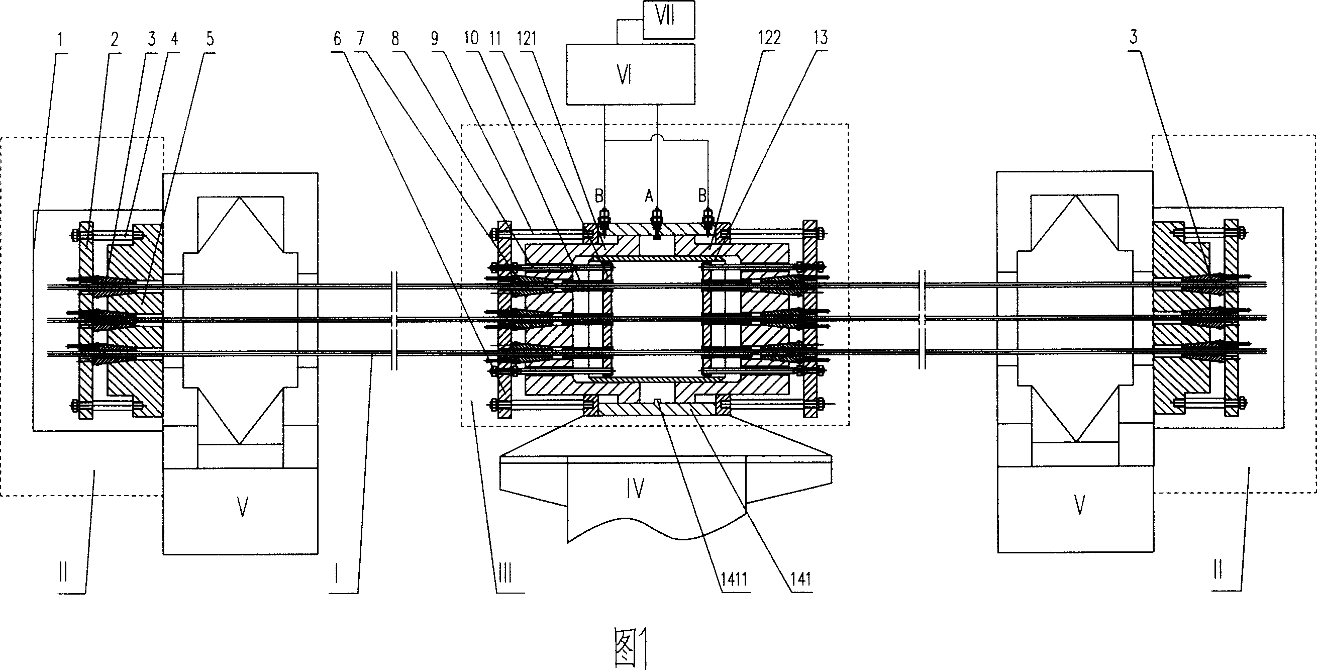
[0041] An anti-slip braking positioning device system, the system is composed of N braking prestressed tendons I and its anchoring device II, braking device III, movable support IV, fixed support V, hydraulic pump station VI and its control system VII The anchoring device II is respectively located at the two ends of the N braking prestressed tendons I, and the braking device III is composed of a brake jack and an anchor loosening device for clamping the prestressed tendons on both sides of the brake jack, The outer wall of the oil cylinder of the brake jack is fixedly connected with the movable support IV, and the N brake prestressed ribs I pass through the anchor holes on the pistons 121, 122 and the anchor loosening device is fixed on the fixed support V in parallel by the anchoring device II. The moving device III is connected with the hydraulic pump station VI through the oil circuit, and the hydraulic pump station VI is connected with the control system VII;

[0042] The...

Embodiment 2

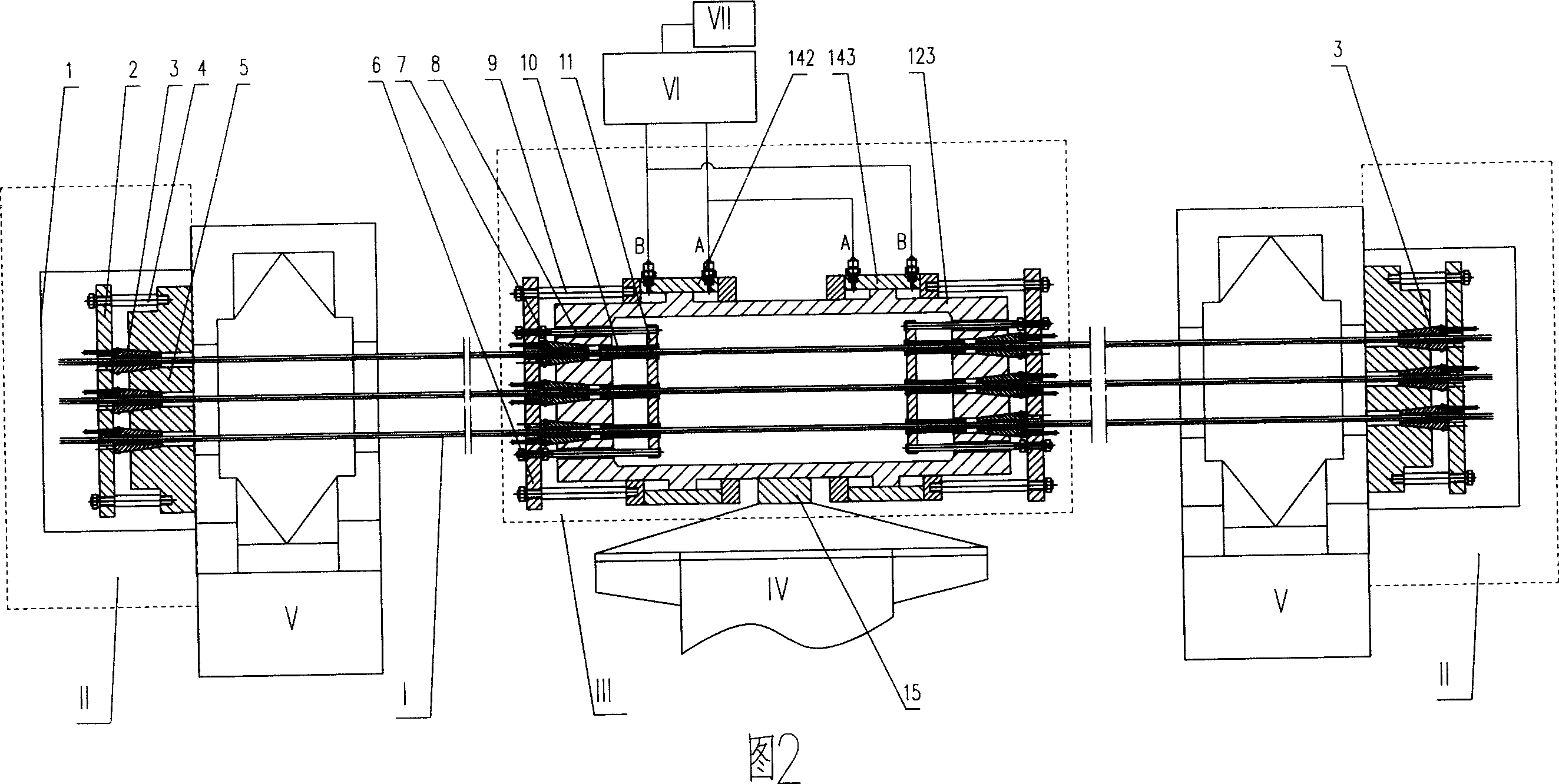
[0046] An anti-slip brake positioning device system, the basic structure of which is the same as that of Embodiment 1, the difference being that the brake jack of the brake device III consists of a piston 123 and two pistons with opposite directions of movement that are sleeved outside the piston 123. Oil cylinders 142, 143 are formed, and there is a connection device 15 in the middle part of the piston outer wall of the brake jack, and the piston is fixedly connected with the movable support IV through the connection device 15 (referring to Fig. 2 ).

Embodiment 3

[0048] The anti-slip braking positioning device system described in the first embodiment above is used in the anti-slip braking or positioning method. It adopts hydraulic prestressing technology to clamp the anchor loosener clamp by controlling the reciprocating movement of the brake jack piston or oil cylinder. Tightening or loosening the prestressed tendons to realize the braking or releasing of large-scale directional mobile equipment or the positioning or releasing of large-scale equipment, it includes the following steps:

[0049] A. System installation:

[0050] ①Prepare the fixed support V, the movable support IV and select the positions for the fixed support V, the hydraulic pump station VI and the control system VII;

[0051] ②Connect a certain part of the braked equipment or the positioned equipment with the movable bracket IV;

[0052] ③Fixly connect the oil cylinder 141 of the brake jack of the brake device III with the movable support IV;

[0053] ④Through the N...


PUM


Abstract

This anti-slippery braking and positioning system and its application method relates to an anti-slippery braking device, a positioning equipment and usage, with the system made of N pieces of braking prestress bars and anchorage device, braking device, active support, fixing support, hydraulic pump station and its control system; The anchorage system is located at both ends of the N pieces of braking prestress bars, the braking device is made of a braking jack and clamping anchor releasing device at its both ends, with the braking jack's oil tank or the piston outside wall fastened with the active support, and the braking prestress bar fasten parallelly on the fixing support through the anchor hole of the piston and clamping anchor releasing device. Under the control of the system, piston or oil tank of the braking jack moves back and forth to make the clamping anchor release device clamp or release the prestress bar to realize the braking or braking removal or positioning or positioning removal of the equipment. This system is powerful in braking and positioning force with good effect and simple and convenient operation.

Description

Technical field: [0001] The invention relates to an anti-slip braking and positioning device and its application, in particular to an anti-slip braking positioning device system using hydraulic prestressing technology and its application. Background technique: [0002] In the braking device of directional mobile equipment, the brake in the form of a brake hoop is the most common braking method. The brake is a device that controls mechanical movement in the braking device, and it is mainly used to absorb the energy generated by the movement when braking. Mechanical brakes are the most common. In moving machines, the brakes work on rotating machine parts through mechanical, hydraulic, aerodynamic or electronic contact methods to absorb mechanical energy, that is, through a The mechanical friction between the rotating metal element and a non-rotating brake element converts the kinetic energy of the rotating metal element into heat energy and transfers it out. However, when us...

Claims


Application Information

Patent Timeline
IPC IPC(8): B66F3/24
Inventor 刘显晖严李荣唐祖文谭柳芳黄颖杨双华
Owner LIUZHOU OVM MASCH CO LTD
Why Eureka
Try Eureka