
Floor panel

A floor and support plate technology, applied in the field of floor panels, can solve problems such as wear and tear

Inactive Publication Date: 2007-02-28
AKZENTA PANEELE PROFILE GMBH
View PDF0 Cites 4 Cited by
  • Summary
  • Abstract
  • Description
  • Claims
  • Application Information

AI Technical Summary

Problems solved by technology

[0009] The disadvantage of the two solutions mentioned is that the surface of the relief-like structure consists of a particle-free material up to a certain depth
This particle-free material wears out quickly when the floor panels are in use

Method used


Image

  • Floor panel
  • Floor panel
  • Floor panel

Examples


Embodiment Construction

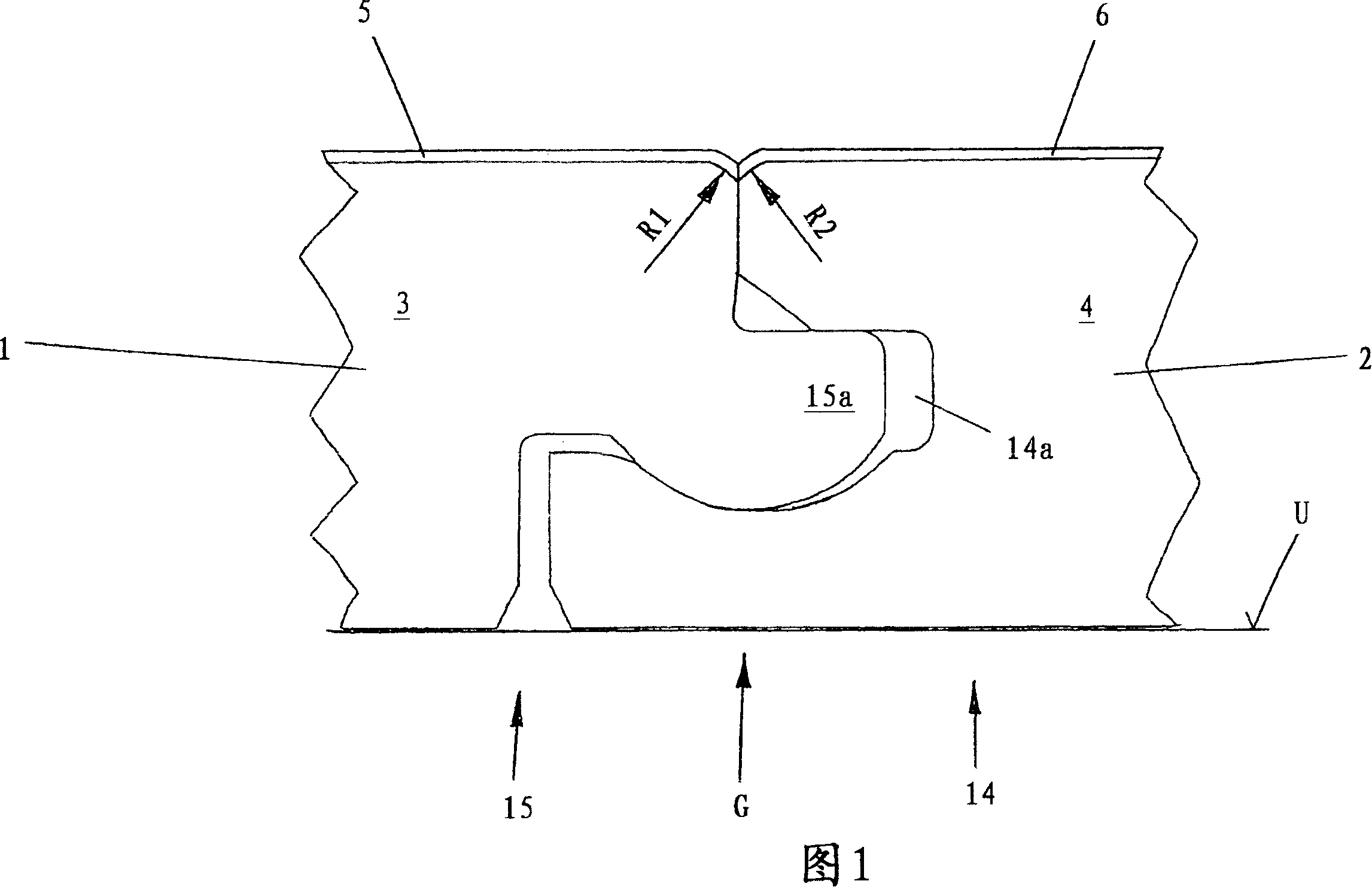
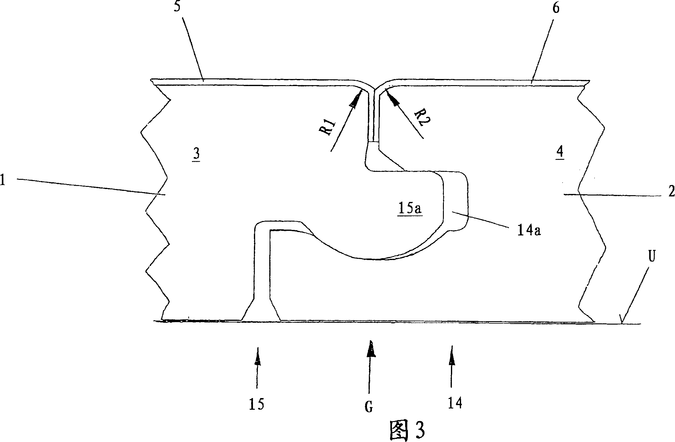
[0033] FIG. 1 shows two interlocking floor panels 1 and 2 according to the invention. Each floor panel 1 or 2 has complementary interlocking profiles on opposite edges, so that the profile of one edge of the floor panel matches the profile of the opposite edge so that it is always possible A similar floor panel is fastened to the laid floor panel. The floor panel 1 therefore has a groove profile (not shown) on the edge facing away from the tongue profile 15 , while the floor panel 2 has a groove profile (not shown) opposite its groove surface 14 .

[0034] The two floor panels 1 and 2 have a carrier plate 3 or 4 on which a service floor 5 or 6 is arranged.

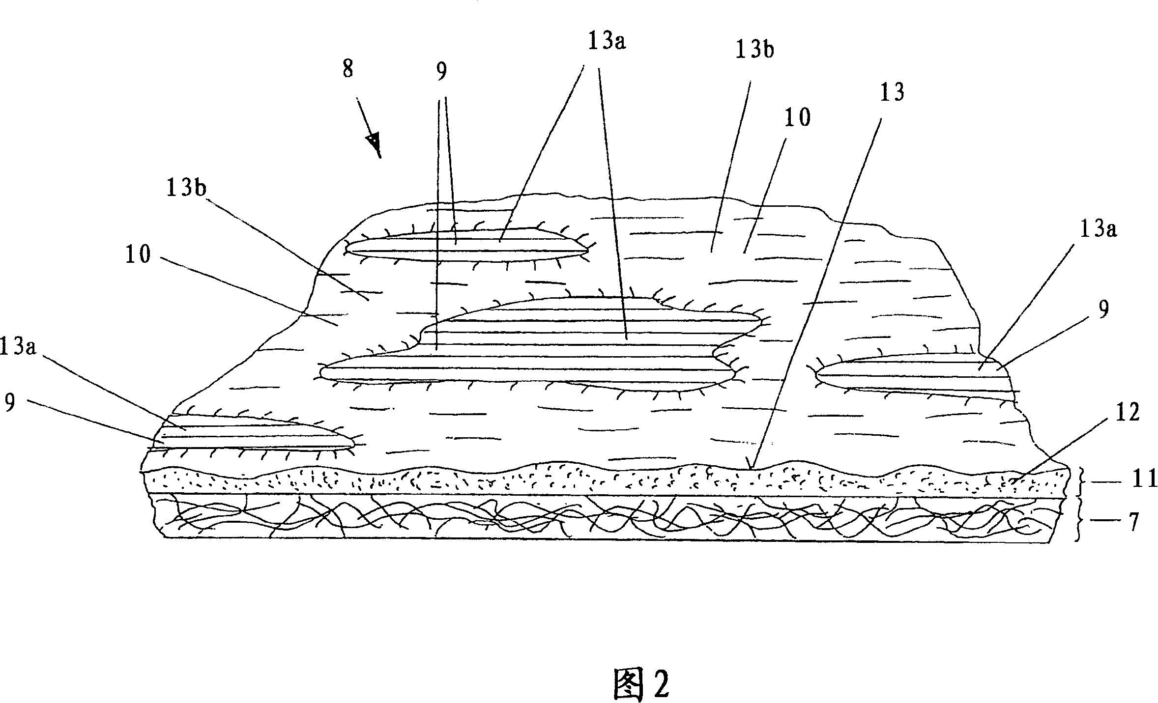
[0035] In order to illustrate the structure of the use layer 5 or 6, FIG. 2 schematically shows part of the use layer. Accordingly, the layer used is paper 7 which is printed with a decorative pattern 8 and which can be referred to as patterned decorative paper 7 . The pattern pattern 8 is divided into different pattern...


PUM


Abstract

The invention relates to a floor panel (1, 2) comprising a carrier plate (3, 4) to which a useful layer (5, 6) provided with a decorative image divided into various sections is applied, said decorative image being protected from wear by abrasionproof particles. The surface of the useful layer has a relief of recesses and raised parts. The recesses comprising certain image sections of the decorative image are surrounded by the raised parts comprising other image sections of the decorative image, said decorative image being coated with a transparent layer of lacquer. According to the invention, the recesses of the relief are produced by a chemical reacting with the lacquer, and the abrasionproof particles are contained in the layer of lacquer.

Description

technical field [0001] The invention relates to a floor panel comprising a support plate on which a use layer is applied, the use layer having a pattern decoratively divided into different pattern areas, wherein the decorative pattern is achieved by means of wear-resistant particles To prevent abrasion, and the surface of the application layer has a relief-like structure comprising depressions and elevations, wherein the depressions overlap defined design areas and the elevations overlap other design areas of the decorative design. Background technique [0002] In order to imitate wood surfaces, ceramic surfaces or rock surfaces, so-called laminated boards are known from which floor panels are made. Laminates usually have a service layer consisting of at least two superimposed paper layers, which is placed on a support board made of wood. As the wood, medium-density or high-density fiberboard, particle board, or the like is used. In most cases, large-area panels are presse...

Claims


Application Information

Patent Timeline
Patent Type & Authority Applications(China)
IPC IPC(8): B32B3/00B44C5/04E04F15/00E04F15/024E04F15/04
CPCE04F15/04B44C5/0476E04F15/02033E04F2201/0153
Inventor R·艾泽曼
Owner AKZENTA PANEELE PROFILE GMBH
Learn More