
Method and device for improving straight line degree measurement sensitivity

A measurement device and sensitivity technology, applied in the field of photoelectric detection, can solve problems such as difficulty in meeting high precision and ultra-high precision, and achieve the effects of increasing anti-interference ability and stability, improving measurement sensitivity, and improving system measurement sensitivity.

Inactive Publication Date: 2007-02-28
BEIJING JIAOTONG UNIV
View PDF1 Cites 17 Cited by
  • Summary
  • Abstract
  • Description
  • Claims
  • Application Information

AI Technical Summary

Problems solved by technology

However, this method is difficult to meet the requirements of high precision and ultra-high precision

Method used


Image

  • Method and device for improving straight line degree measurement sensitivity
  • Method and device for improving straight line degree measurement sensitivity
  • Method and device for improving straight line degree measurement sensitivity

Examples


Embodiment 1

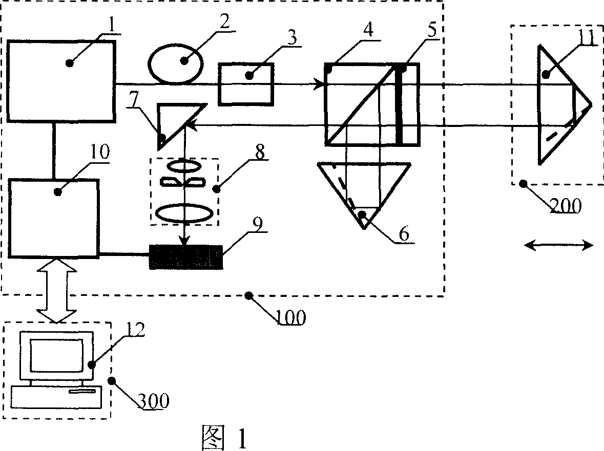
[0027] Embodiment one (as shown in Figure 1):

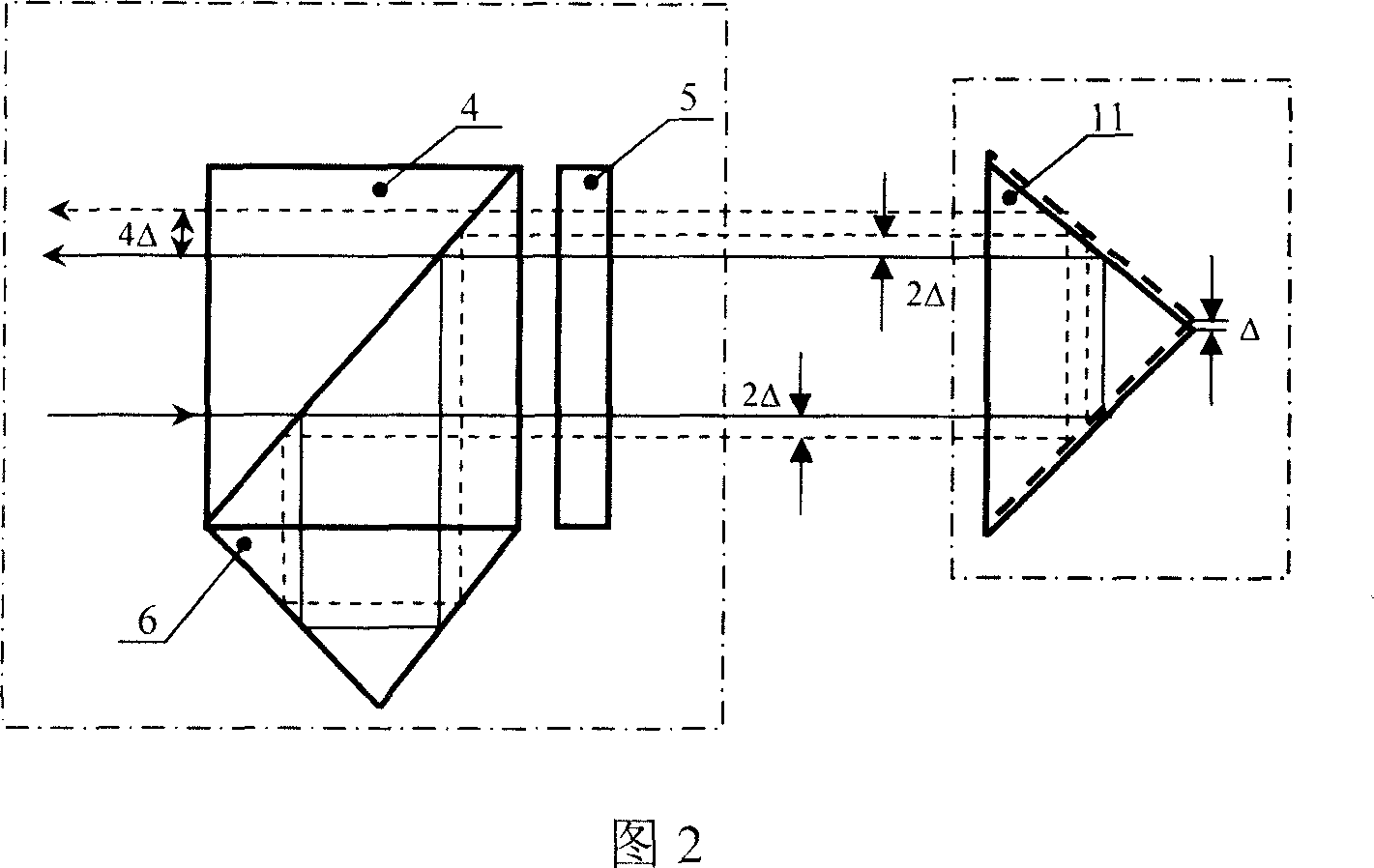
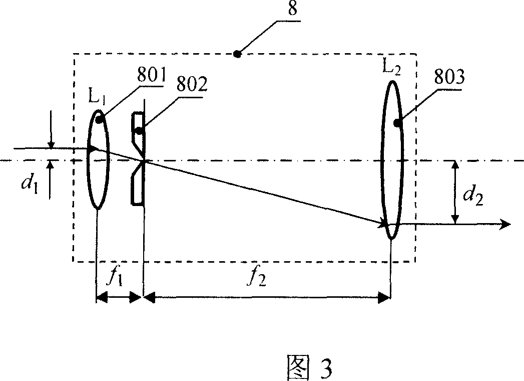
[0028] The high-sensitivity straightness error measurement system in the system is a high-stable laser beam emitted by the semiconductor laser 1 in the fixed unit 100. After being collimated by the single-mode fiber 2 and the collimator lens 3, it is incident on the polarization beam splitter 4, and the incident light After passing through the polarizing beam splitter 4, it becomes linearly polarized light. The linearly polarized light passes through λ / 4 After wave plate 5, it becomes circularly polarized polarized light. After being reflected by the corner cube prism 11 incident into the mobile unit 200, it passes through λ / 4 After the wave plate, the circularly polarized light becomes linearly polarized again, but its polarization direction is rotated by 90° angle. The light is reflected to another reflector 6 through the polarizing beam splitter, so that the light passes through the corner cube prism 11 of the primary movin...

Embodiment 2

[0037] Embodiment two (as shown in Figure 4):

[0038] The difference from Embodiment 1 is that a reflector 11 is added to the mobile unit 200, and a set of polarization beam splitter 4, λ / 4 wave plate 5, reflector 6, and reflector 13. On the basis of Embodiment 1, the measurement sensitivity of the system is doubled again.

Embodiment 3

[0039] Embodiment three (as shown in Figure 5):

[0040] The difference from Embodiment 1 is that a reflective unit 14 (composed of a retroreflector and a reflector) is used to make the measuring light path pass through the moving target mirror four times to achieve the same sensitivity multiplication effect as Embodiment 2, which is similar to that of Embodiment 2. The difference is to make the system more compact.


PUM


Abstract

The invention relates to a method for improving the sensitivity of linearity test, and a relative device, wherein it is a laser testing system formed by fixed unit, movable unit and computer; it comprises laser emitter, deviation splitter, lambada / 4 wave plate, reflector, photoelectric receiver and signal processor. The optical element sets the testing light to pass the movable target mirror several times, to magnify its testing sensitivity several times; and it sets lens group before the detector, to magnify the sensitivity more. The invention can test two-dimension linearity of straight track real time.

Description

technical field [0001] The invention belongs to the technical field of photoelectric detection, and is especially suitable for measuring the two-dimensional straightness error of the movement or the shape position error (such as straightness, coaxiality, etc.) of a large workpiece when the workpiece or object moves along a certain guide rail. A method and device for improving the sensitivity of straightness measurement. Background technique [0002] Straightness measurement is a common and important measurement item in machining. It mainly includes the measurement of the straightness error of the actual surface of the workpiece and the measurement of the straightness error of the linear guide rail or the automatic correction of the linear motion mechanism. The dual-frequency laser interferometer can achieve high-precision detection of linear displacement errors and angular displacement errors of moving parts, but the instrument is expensive, the measurement cost is high, and...

Claims


Application Information

Patent Timeline
Patent Type & Authority Applications(China)
IPC IPC(8): G01B11/27
Inventor 匡翠方冯其波陈士谦张志峰
Owner BEIJING JIAOTONG UNIV
Learn More