Method and device for producing staple fibers

A short fiber and spinning device technology, applied in the field of short fiber manufacturing, can solve the problems of low manufacturing capacity and achieve the effect of short replacement time

Inactive Publication Date: 2007-02-21
SAURER GMBH & CO KG
View PDF1 Cites 3 Cited by
  • Summary
  • Abstract
  • Description
  • Claims
  • Application Information

AI Technical Summary

Problems solved by technology

However, this method basically has the disadvantage of low manufacturing capacity, because both the extraction of the tow from the spinning unit and the drawing of the tow must be carried out in the processing unit

Method used


Image

  • Method and device for producing staple fibers
  • Method and device for producing staple fibers
  • Method and device for producing staple fibers

Examples


Embodiment Construction

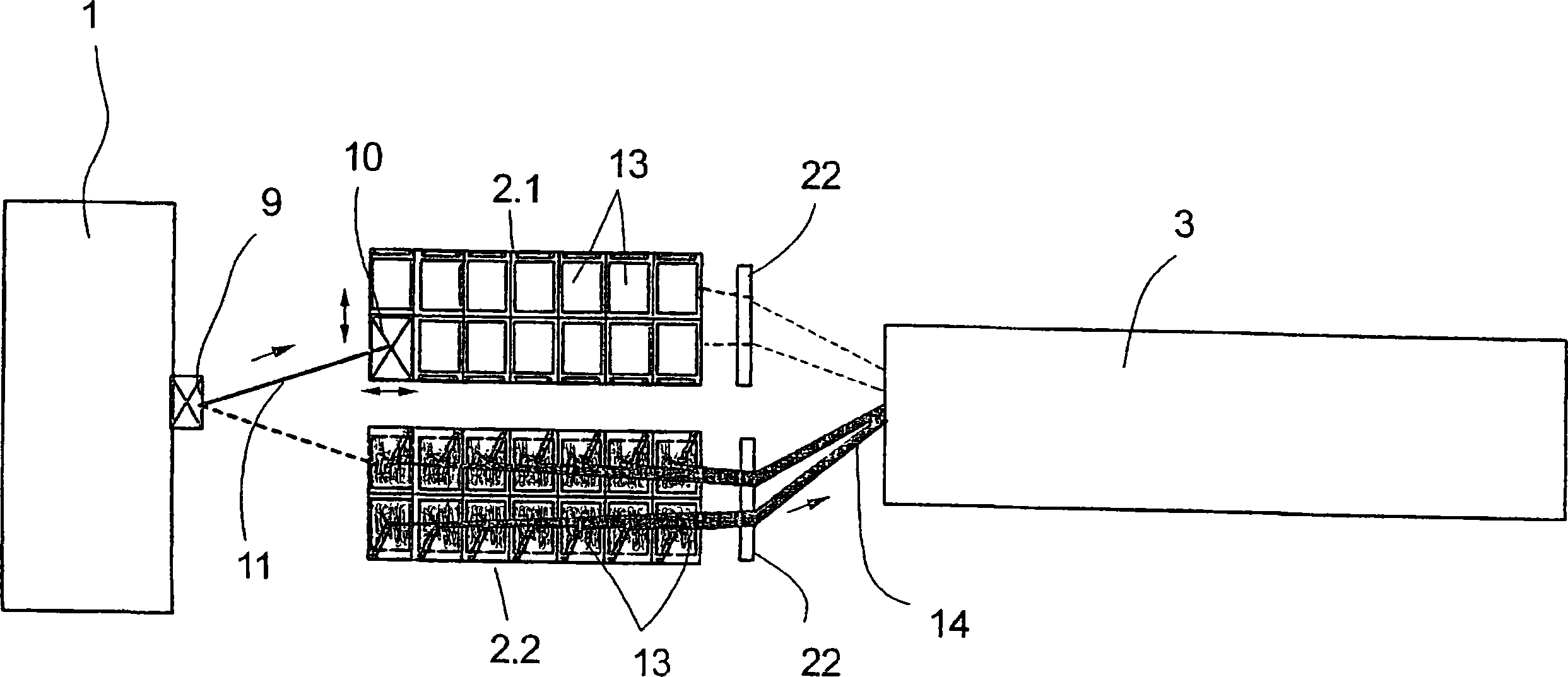
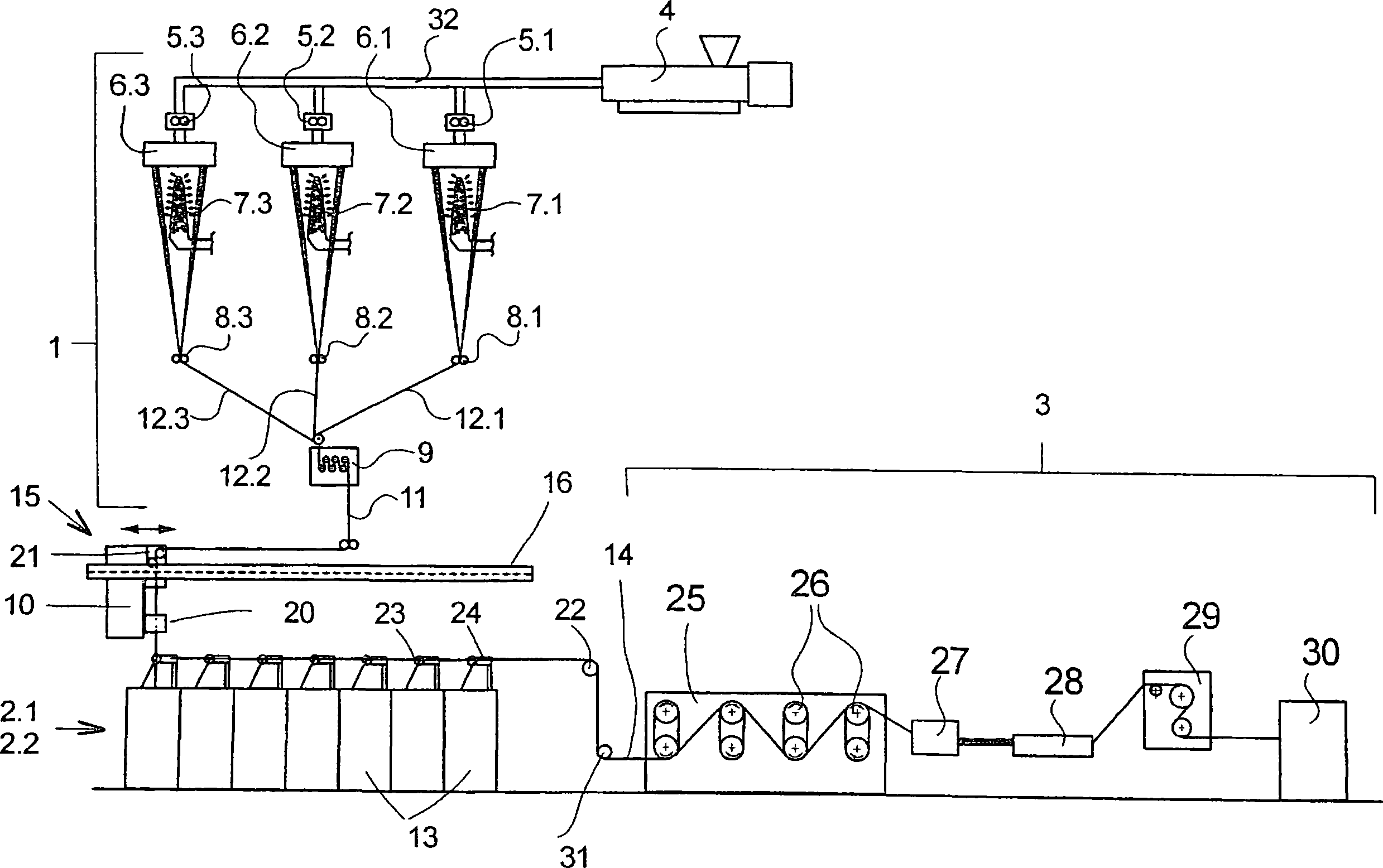
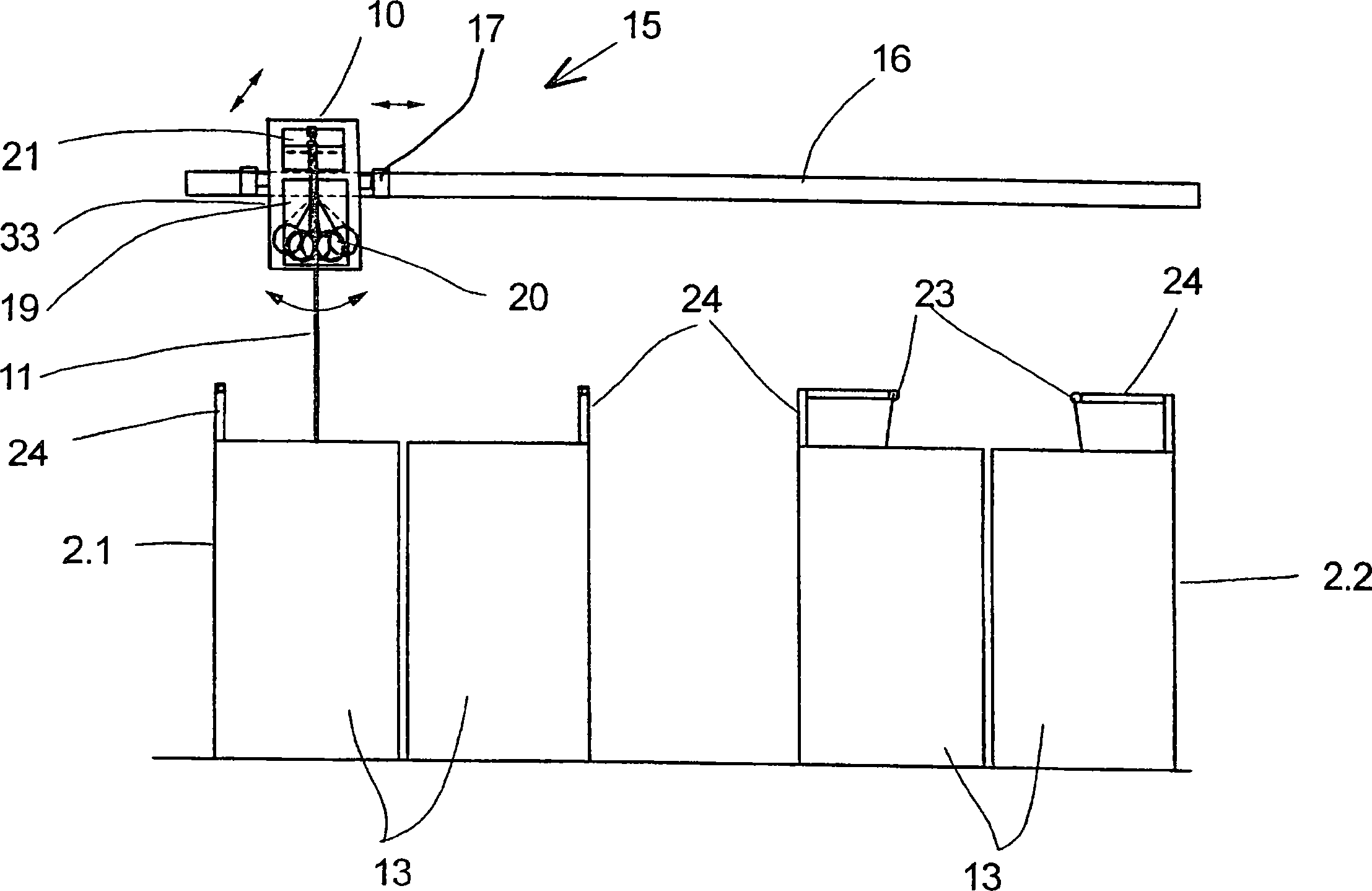
[0023] figure 1 An embodiment of the device according to the invention is shown in top view in . The device comprises a spinning device 1 , two can creels 2 . 1 , 2 . 2 interacting with the spinning device and a treatment device 3 . The spinning device 1 includes a plurality of spinning stations for melt-spinning a plurality of monofilament strands, and the monofilament strands are combined into a tow 11 by a drawing mechanism 9 . The tow 11 reaches the laying device 10 which is guided in a positionable manner above the can creels 2.1 and 2.2 via the draw-off mechanism 9 . The can creels 2 . 1 and 2 . 2 comprise a plurality of cans 13 . exist figure 1 In the arrangement shown, the depositing device 10 is assigned to the can creel 2.1, in which case the first can 13 of the can creel 2.1 is filled. The laying device 10 can be guided to each can of the can creel 2.1 so that the cans 13 of the can creel 2.1 can be filled sequentially with tow.

[0024] The cans 13 held in the...


PUM


Abstract

The invention relates to a method and a device for producing staple fibers. According to the invention, in a first process step, a tow from molten filament strands is produced and deposited in a tow can. In a second process step, the tows of a plurality of tow cans of a can creel are withdrawn, treated and cut to give staple fibers. In order to reduce the interruption times between the first process step and the second process step, the tow, in the first process step, is deposited directly into the tow can retained in the can creel, and the tow cans of the can creel are filled one after the other.

Description

technical field [0001] The invention relates to a method for producing staple fibers according to the preamble of claim 1 and a device for carrying out the method according to the preamble of claim 8 . Background technique [0002] Basically two different types of methods and devices for producing staple fibers are known. In a first type of method and apparatus, staple fibers are produced in a two-stage process. For this purpose, a plurality of monofilament strands are spun from the polymer melt in a first process step and combined to form a tow after cooling. At the end of the first processing step the tow is laid down in a drum for storage. In the second processing step, the processing device draws a plurality of tows from several cans held in a creel (Kannegatter), combines them into a total filament (Gesamttow), processes it, and then cuts it into short fibers. This two-stage treatment is used in particular for processing very coarse total titers, for example greater...

Claims


Application Information

Patent Timeline
Patent Type & Authority Applications(China)
IPC IPC(8): D01D5/26D01D7/00D01D10/04B65H54/78
CPCB65H2701/31D01D7/00D01D5/26B65H54/78D01D10/049
Inventor C·福格特伦德A·格林H·克若帕特B·舍恩纳格尔M·申肯
Owner SAURER GMBH & CO KG
Why Eureka
Try Eureka