Sealed type compressor

A compressor and sealed technology, which is applied in the direction of liquid variable capacity machinery, mechanical equipment, variable capacity pump components, etc., can solve the problems of reduced production efficiency, loss of piston sliding surface, difficulty in maintaining the accuracy of the sphere, etc., to achieve improved Efficiency and sliding loss reduction effect

Active Publication Date: 2007-02-21
지엠씨씨앤드웰링어플라이언스컴포넌트(타일랜드)컴퍼니리미티드
View PDF4 Cites 6 Cited by
  • Summary
  • Abstract
  • Description
  • Claims
  • Application Information

AI Technical Summary

Problems solved by technology

At this time, the production efficiency has decreased
[0015] On the other hand, if the spherical portion and the rod portion are formed integrally, it will be difficult to maintain the accuracy of the spherical portion. Therefore, not only loss is likely to occur on the sliding surface of the piston, but also the reliability caused by the progress of wear may be caused. reduction of

Method used


Image

  • Sealed type compressor
  • Sealed type compressor
  • Sealed type compressor

Examples


Embodiment Construction

[0053] Hereinafter, embodiments of the present invention will be described with reference to the drawings.

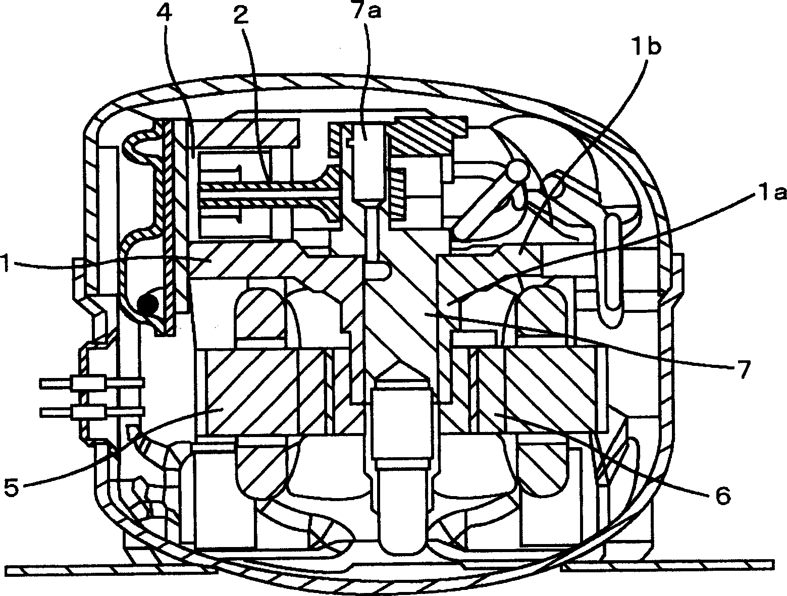
[0054] figure 1 It is a vertical cross-sectional view of a hermetic compressor according to an embodiment of the present invention. The hermetic compressor of this embodiment is a reciprocating compressor. The piston 4 reciprocates in the cylinder 1 to form a compression mechanism. The cylinder 1 is integrally formed by the bearing part 1a and the frame 1b disposed in the airtight container. The lower part of the frame 1b is provided with a stator 5 and a rotor 6 constituting a motor as a motor, and a crank pin 7a is provided at a position eccentric from the rotation center of the crankshaft 7 .

[0055] The crankshaft 7 extends upward from the lower portion of the frame 1b through the bearing portion 1a of the frame, and the crank pin 7a is provided on the upper side of the frame 1b. The lower part of the crankshaft 7 is directly connected to the rotor 6, and the cr...


PUM


Abstract

The invention provides a compressor increased in efficiency by reducing sliding loss. In this hermetically sealed compressor, compression elements and electric elements are stored in a hermetically sealed container, and a crankshaft 7 driven by the electric elements is connected to a piston 4 through a connecting rod 2 by a ball joint structure. The ball joint structure comprises an inner spherical surface 4a formed on the piston 4, a spherical body part 2a formed on the connecting rod 2, and a rotation restriction part 10d formed separately from the piston 4 and the connecting rod 2. The rotation restriction part 10d is installed on the piston 4 side but the connecting rod 2 side to restrict the relative rotation of the piston 4 and the connecting rod 2. A ferrous sintered material sealed by an oxide film is used for the piston 4 and the connecting rod 2.

Description

technical field [0001] The present invention relates to a hermetic compressor used in a refrigerator, a room air conditioner, etc., and more particularly to a hermetic compressor having a reciprocating piston. Background technique [0002] In a hermetic compressor having a reciprocating piston, a structure is used in which a crankshaft and a piston are connected by a connecting rod, and the motion of a rotary shaft in rotary motion is converted into reciprocating motion. Among them, as a connection structure between a piston and a connecting rod, a structure connected by a radial bearing as described in Patent Document 1 is known. [0003] In the structure of patent document 1, a piston pin is used for the connection part of a piston and a connecting rod, and the bearing structure which forms this piston pin as a shaft connects both. [0004] In addition, as another connecting structure of the piston and the connecting rod, there is known a so-called ball joint structure co...

Claims


Application Information

Patent Timeline
IPC IPC(8): F04B39/00
Inventor 野崎务三品将利佐藤真一长尾智大中岛昌一
Owner 지엠씨씨앤드웰링어플라이언스컴포넌트(타일랜드)컴퍼니리미티드
Why Eureka
Try Eureka