
Hermetic compressor

A compressor and hermetic technology, applied in mechanical equipment, machines/engines, liquid displacement machines, etc., can solve problems such as narrow oil passages, deterioration, wear, etc., improve reliability and capacity, and reduce sliding losses Effect

Inactive Publication Date: 2012-06-13
ジーエムシーシーアンドウェリングアプライアンスコンポーネントタイランドカンパニーリミテッド
View PDF3 Cites 0 Cited by
  • Summary
  • Abstract
  • Description
  • Claims
  • Application Information

AI Technical Summary

Problems solved by technology

Therefore, there is a possibility that the contact surface pressure at the corner increases, causing wear and deterioration
[0009] In addition, in the connection structure described in Patent Document 3, the passage of the oil supplied to the ball joint mechanism is narrow, so there is a possibility that the lubricating oil is not smooth enough.
If the flow of lubricating oil is blocked, the temperature of the spherical bearing may rise and damage may occur

Method used


Image

  • Hermetic compressor
  • Hermetic compressor
  • Hermetic compressor

Examples


Embodiment 1

[0079] It can be seen from the above results that in order to suppress the wear caused by the corners of the flow path 2f, the effective measure is to increase the small radius portion 2d and avoid the contact between the corners of the flow path 2f and the inner spherical surface 4a of the piston 4. At this time, it is necessary to consider the surface The local concentration of pressure and the increase of average surface pressure.

[0080] In this embodiment, in order to suppress the surface pressure between the outer spherical end 2a" and the inner spherical surface 4a, the corner of the outer spherical end 2a" is obtuse, or the chamfer R is provided so that it does not become an edge. According to this configuration, it is possible to avoid contact between the flow path 2f and the inner spherical surface 4a, and to reduce abrasion due to the outer spherical surface end portion 2a" where surface pressure tends to concentrate.

[0081] In addition, as described above, since...

Embodiment 2

[0086] Next, a test was also performed on an example in which the sizes of the spherical portion 2a and the inner spherical surface 4a were the same as in Example 1, but the lubricating oil flow path 2f was different. In Example 2, the hole 2fb was used as the flow path 2f.

[0087] Also, in the case where the small-radius portion 2d is completely surrounded by the outer spherical surface of the spherical portion 2a, it is difficult to provide a flow path between the small-radius portion 2d and the surface 2a' using a groove. In this case, if the flow path 2f is provided by using the hole 2fb, the outflow and inflow path of lubricating oil can be ensured.

[0088] In this example, a hermetic compressor provided with a circular hole 2fb with a diameter of 1mm was produced, and when an actual equipment test was carried out, it was found that the ball joint structure did not disengage, and that the outer spherical end 2a" was not seen. Aggravated by excessive wear, the result of...


PUM


Abstract

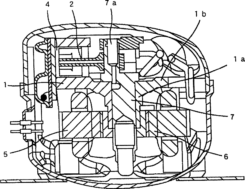
The present invention provides a hermetic compressor which can reduce the slip loss and improve reliability and ability. The hermetic compressor accommodates a compress unit and an electric unit in a hermetic container, an eccentric part (7a) and a piston (4) disposed on a drive shaft driven by the electric unit are linked by a link rod (2), the adopted constitution has an inner ball surface (4a)disposed on the piston (4) and a ball part (2a) of the link rod (2) enclosed by the inner ball surface (4a) and linked to the piston (4) by a ball socket joint mechanism, the front end of the ball part (2a) has a small radius part (2d) with a distance to the center of the ball part (2a) smaller than the radius of the ball part (2a).

Description

technical field [0001] The present invention relates to a hermetic compressor used in refrigerators, room air conditioners, etc., and more particularly to a hermetic compressor having a reciprocating piston. Background technique [0002] As a coupling structure of a piston and a connecting rod of a compressor, as in Patent Document 1, a coupling structure using a radial bearing is known. In addition, as in Patent Document 2 and Patent Document 3, ball joint structures connected by spherical bearings are known. In Patent Document 2, the inner spherical surface (ball seat) of the piston and the ball portion of the connecting rod are partially cut, the ball portion of the connecting rod is inserted into the ball seat, and the piston is rotated to connect them. In addition, Patent Document 3 adopts a structure in which the inner spherical surface provided on the piston is molded through plastic working. [0003] Patent Document 1: JP-A-2004-27969 [0004] Patent Document 2: J...

Claims


Application Information

Patent Timeline
Patent Type & Authority Patents(China)
IPC IPC(8): F04B39/00
CPCF04B35/04F04B39/0005F04B39/0022F04B39/023F04B39/0276F04B39/0292F16C11/06F16C11/068Y10S417/902
Inventor 野崎务绀野元长尾智大
Owner ジーエムシーシーアンドウェリングアプライアンスコンポーネントタイランドカンパニーリミテッド
Learn More