
Air light catalytic purifier of moderate chemical pollution

A technology for chemical pollution and purification equipment, applied in chemical instruments and methods, separation of dispersed particles, separation methods, etc.

Inactive Publication Date: 2007-01-17
WUHAN UNIV OF TECH
View PDF5 Cites 7 Cited by
  • Summary
  • Abstract
  • Description
  • Claims
  • Application Information

AI Technical Summary

Problems solved by technology

[0007] The purpose of the present invention is to provide an advanced, low-cost, high-efficiency, rapid purification of moderately chemically polluted air for the main technical problem that the current photocatalytic technology cannot be low-cost, high-efficiency, and rapidly purify moderately chemically polluted air Photocatalytic purification equipment

Method used


Image

  • Air light catalytic purifier of moderate chemical pollution

Examples


Embodiment Construction

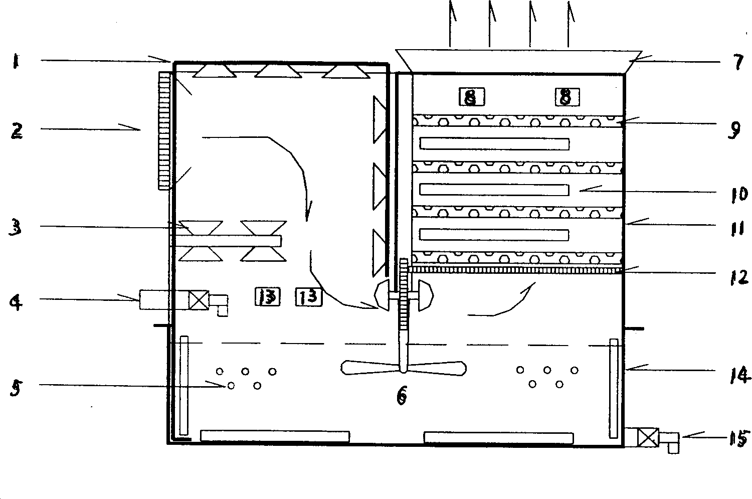
[0021] Moderate chemical pollution air photocatalytic purification equipment example structure of the present invention is as figure 1 Shown: Process:

[0022] The air polluted with medium concentration enters the purification equipment from the air inlet 2, and after being roughly filtered by the mesh screen, it enters the spray system 1 equipped with the spray head 3, and quickly removes the part of the polluted air that can be dissolved or absorbed by water. substance. And the spray liquid that dissolves or adsorbs some pollutants is stirred in the liquid phase photocatalyst and cavity 14 through continuous gas stirring 6 to obtain floating photocatalytic glass beads or magnetic photocatalytic glass beads 5 for purification treatment, magnetic photocatalytic The catalytic glass beads 5 are purified and recovered by the electromagnetic induction system; the low-concentration polluted air purified by the spray water is sterilized by the ultraviolet lamp 10 and the ozone gene...


PUM


Abstract

An optically catalytic cleaning apparatus for the air polluted chemically to the medium extent is composed of a casing, a water showering-circulating system consisting of cavity, air inlet filter, showering head and water inlet tube, a solid-phase optical catalyzer consisting of cavity, composite nano-TiO2 photocatalyst, carrier, UV lamp, water-air separator, and negative ion generator, a liquid-phase optical catalyzer consisting of cavity, photocatalytic glass microbeads, gas stirring rod, water outlet system and UV lamp, and an ozone generator.

Description

technical field [0001] The invention relates to photocatalytic purification equipment for chemically polluted air, in particular to a photocatalytic purification unit for moderately chemically polluted air combined with ultraviolet lamps, ozone generators, negative ion generators, water spray treatment and activated carbon adsorption purification units. Catalytic purification equipment. Background technique [0002] The principle of removing organic pollutants in polluted air by using photocatalytic technology is: using semiconductor TiO 2 When the nanomaterial photocatalyst is excited by ultraviolet light, the high-energy charge electrons-holes, with the participation of oxygen and water, make the adsorption and contact on TiO 2 Organic and inorganic particles on the surface of nanomaterial photocatalysts can be photooxidized, photocatalyzed, photoreduced, and photomineralized into CO 2 、H 2 O, H 2 , N 2 or other intermediate products. [0003] TiO 2 Nanomaterial pho...

Claims


Application Information

Patent Timeline
Patent Type & Authority Applications(China)
IPC IPC(8): B01D53/86
Inventor 董学斌木士春熊威赵国荣刘桂珍陶剑青董毅万敏康强
Owner WUHAN UNIV OF TECH
Learn More