Rotary scalpel head for surgical binder
A technology of rotating cutter head and binding instrument, which is applied in the direction of surgical fixation nails, etc., can solve the problems of unclean removal of excess tissue on the wound surface, excessive force, etc., to reduce tissue stretching wounds, reduce binding force, The effect of safely and reliably cutting tissue
- Summary
- Abstract
- Description
- Claims
- Application Information
AI Technical Summary
Problems solved by technology
Method used
Image
Examples
Embodiment 1
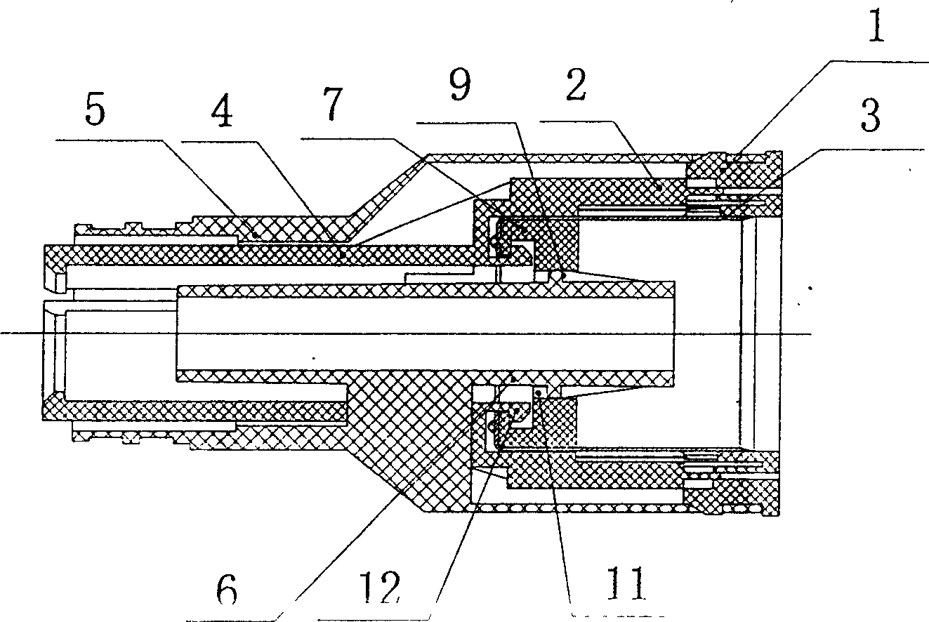
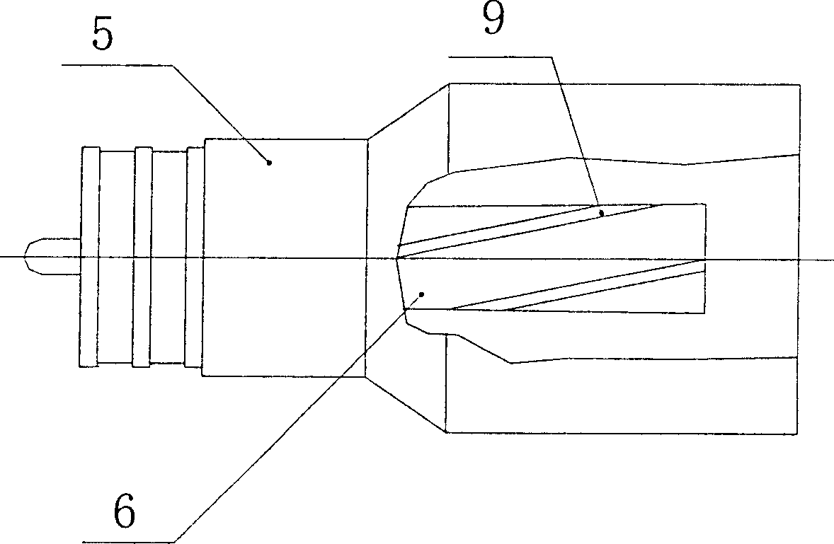
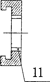
[0033] Embodiment one: if Figure 1-2 As shown, the pusher piece 2 is integrated with the pusher column 4, the screw sleeve 7 is arranged on the inner bottom surface of the ring cutter 3, and the bottom of the front end cavity of the pusher piece 2 is provided with a hook 12 to be connected with the bottom of the ring cutter 3. When the nail push piece 2 is subjected to a forward displacement, it will drive the rotary sleeve 7 and the cutter 3 to move forward, and at the same time, the spiral guide groove 11 of the rotary sleeve 7 cooperates with the spiral guide rail 9 of the anti-expansion tube 6 of the nail barrel function, forcing the swivel 7 to produce rotational motion. Because the rotary sleeve 7 is riveted and fixed with the cutter 3, the cutter 3 rotates together with the rotary sleeve 7. After the binding is completed, the cutter 3 and the rotary sleeve 7 are pulled back in the nail barrel under the action of the barb 12 of the nail pushing piece.
Embodiment 2
[0034] Embodiment two: if Figure 5As shown, the pusher piece 2 and the pusher post 4 are integrated, the screw sleeve 7 is arranged on the outer bottom surface of the annular cutter 3, and the bottom of the front cavity of the pusher piece 2 is provided with a hook 12 and the bottom of the screw sleeve 7 is articulated. When the nail push piece 2 is subjected to a forward displacement, it will drive the rotary sleeve 7 and the cutter 3 to move forward, and at the same time, the spiral guide rail groove 11 of the rotary sleeve cooperates with the spiral guide rail 9 of the anti-expansion tube 6 of the nail barrel , forcing the rotary sleeve 7 to produce rotational motion. Because the rotary sleeve 7 is riveted and fixed with the cutter 3, the cutter 3 rotates together with the rotary sleeve 7. After the binding is completed, the cutter 3 and the rotary sleeve 7 are pulled back in the nail barrel under the action of the barb 12 of the nail pushing piece.
Embodiment 3
[0035] Embodiment three: as Figure 6 As shown, the push nail piece 2 and the push nail post 4 are integrated, the screw sleeve 7 is arranged on the inner bottom surface of the annular cutter, the fixed screw sleeve 13 is fixed on the outer periphery of the stop tube 6, and the outer wall is provided with a spiral guide rail 9, which is fixed on the stop tube 6. On the upper surface of the threaded insert 8 on the pipe 6, a limit fastening nut 10 is arranged. The bottom of the cavity at the front end of the nail push piece 2 is provided with a hook 12 which is hooked with the bottom of the rotary sleeve 7 . When the nail pusher 2 is subjected to a forward displacement, it will drive the rotary sleeve 7 and the cutter 3 to move forward. 7 to generate rotational motion. Because the rotary sleeve 7 is fixed by riveting with the cutter 3, the cutter rotates together with the rotary sleeve 7. After the binding is completed, the cutter 3 and the rotary sleeve 7 are pulled back in...
PUM
 Abstract
Description
Claims
Application Information
 - Generate Ideas
- Intellectual Property
- Life Sciences
- Materials
- Tech Scout
- Unparalleled Data Quality
- Higher Quality Content
- 60% Fewer Hallucinations
Browse by: Latest US Patents, China's latest patents, Technical Efficacy Thesaurus, Application Domain, Technology Topic, Popular Technical Reports.
© 2025 PatSnap. All rights reserved.Legal|Privacy policy|Modern Slavery Act Transparency Statement|Sitemap|About US| Contact US: help@patsnap.com


