Gear change mechanism

A speed change device, gear technology, applied in the direction of gear transmission, transmission, belt/chain/gear, etc., can solve problems such as large space

Active Publication Date: 2007-01-03
QINETIQ LTD
View PDF1 Cites 7 Cited by
  • Summary
  • Abstract
  • Description
  • Claims
  • Application Information

AI Technical Summary

Problems solved by technology

This device is simple, stable and effective, but the problem is that due to the spacing of the gears, the need for jaws on the opposite end of the selector, and the space required for the selector to move back and forth between the gears, this device requires a lot of force in the axial direction. space

Method used


Image

  • Gear change mechanism
  • Gear change mechanism
  • Gear change mechanism

Examples


Embodiment Construction

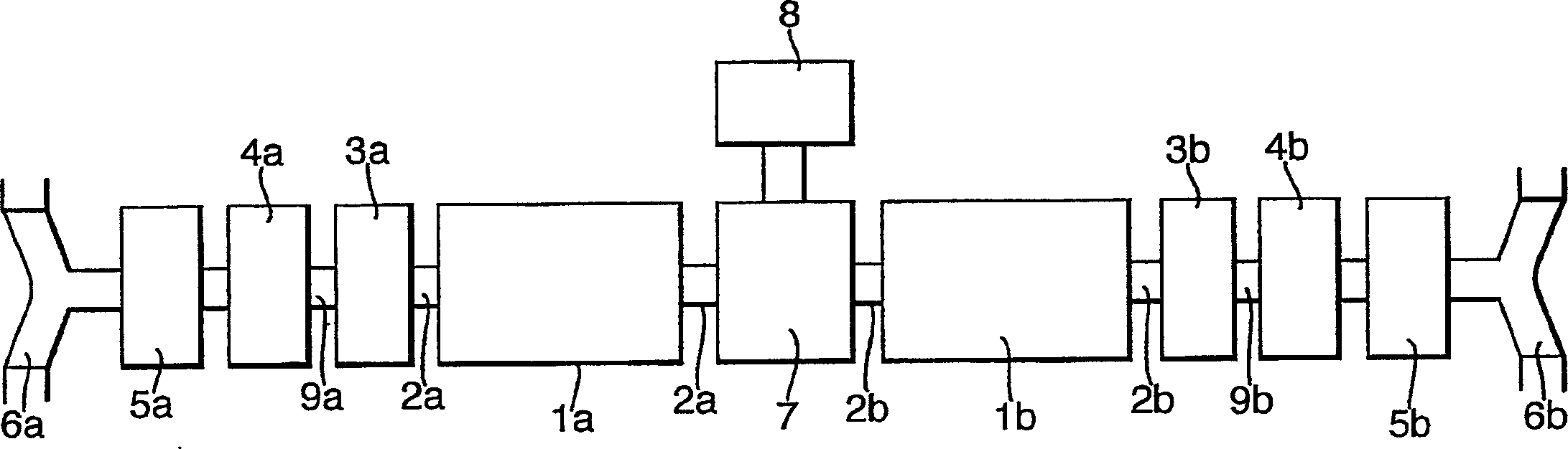
[0014] figure 1 One form of drive is shown diagrammatically with which the variable speed gear drive of the present invention is particularly useful as a track drive for the braked vehicle of WO-02 / 083483. However, it can be understood that the current device is generally applied in gear transmission systems of vehicles or other machines, especially machines that require an axially compact device.

[0015] figure 1 Among them, a transverse drive device includes two propulsion motors 1a and 1b for driving shafts 2a and 2b. Externally to the motor, the transmission comprises on each side a gear change unit 3a, 3b, a brake 4a, 4b and a final drive gear reducer 5a, 5b, all located within the vehicle housing such that the respective track drive sprockets 6a and 6b are respectively located on opposite sides of the vehicle. Inside the motors, the shafts 2a and 2b are connected to a controlled differential 7 driven by a steering motor 8, all of which is described in WO-02 / 083483 an...


PUM


Abstract

A gear change mechanism coupling a pair of shafts (2) and (9) employs a planetary gear set comprising a sun gear (10) fast with shaft (2), planet gears (12) in a planet carrier (15), and an annulus or ring gear (17), the latter being fixed. A selector hub (19) slidable on shaft (9) has sets of radially spaced dogs (22) and (24) to engage with corresponding dogs (29) and (34) on the planet carrier and sun gear respectively, so as to couple the shafts (2) and (9) at two different ratios depending on the axial position of the selector hub. This results in a more axially compact package than conventional dog clutch gear changers. In an alternative embodiment a reversing mechanism is provided by fixing the planet carrier and engaging the selector hub with the sun gear or annulus depending on its axial position.

Description

technical field [0001] This invention relates to gear transmissions, particularly those employing dog clutches. The device according to the invention can be used in various vehicular applications or on devices that require a simple, stable and compact gearbox, but also in particular in battle tanks, stamping machines or some other as described in WO-02 / 083483 on a vehicle with brakes equipped with a drive unit. Background technique [0002] Constant mesh transmissions typically use dog clutches when selecting different gear ratios. In a typical setup, the gear selector is splined to the output shaft and is free to slide axially along the shaft, but the shaft must always rotate with the selector. Gears driven in different ratios by the engine or other starter are coaxially positioned on either side of the selector. The opposite faces of the selector and gear are formed with complementary axial projections and / or grooves (detents) so that when the selector is driven from an...

Claims


Application Information

Patent Timeline
Patent Type & Authority Applications(China)
IPC IPC(8): F16H3/54F16D11/14
CPCF16H3/54
Inventor R·W·汤普逊
Owner QINETIQ LTD
Why Eureka
Try Eureka