Burst light-emitting signal power testing method and apparatus in PON system

A power test and optical signal technology, applied in the field of optical communication, to reduce processing difficulty, reduce product cost and power consumption, and facilitate easy production performance

Active Publication Date: 2007-01-03
GUANGXUN SCI & TECH WUHAN
View PDF0 Cites 16 Cited by
  • Summary
  • Abstract
  • Description
  • Claims
  • Application Information

AI Technical Summary

Problems solved by technology

[0006] The purpose of the present invention is to provide a method and device for testing burst optical signal power in a PON system to solve the technical problem of correctly testing burst optical signal power in a PON system

Method used


Image

  • Burst light-emitting signal power testing method and apparatus in PON system
  • Burst light-emitting signal power testing method and apparatus in PON system
  • Burst light-emitting signal power testing method and apparatus in PON system

Examples


Embodiment Construction

[0034] Device circuit block diagram of the present invention is as image 3 shown. The concrete realization process of method of the present invention is as follows:

[0035] The preamplifier circuit U2 composed of a broadband operational amplifier converts the optical signal received by the photodetector PIN tube U1 into a voltage signal with a linear correspondence;

[0036] After the voltage signal is shaped by the signal shaping circuit U3, it is respectively sent to the input end of the sample and hold circuit U7 and the positive end of the comparator of the comparison circuit U4;

[0037] At this time, U7 is in the signal sampling stage (the rising edge trigger U6 is initialized by the signal processing control circuit U8 so that U7 is in the sampling stage), and the negative terminal of the comparator of the comparison circuit U4 is connected to a reference voltage as the judgment of whether there is light or not on the line. When there is no light, the positive termi...


PUM


Abstract

This invention discloses a method and a device for testing powers of burst optical signals in a PON system, which utilizes signal transformation, shaping, comparison, delay trigger and signal sample to maintain optical signal packets on a technical capture circuit to turn high frequency burst optical signals to low frequency maintained electric signal pulse level to be sampled to get a mean optical power of the single signal packet so as to get the actual light emitting power of burst signals on the circuit, in which, the circuit is composed of a pre-amplifying, signal shaping, signal comparison, pulse time delay, trigger control, signal sample maintenance and signal process control, which only captures and samples the optical signals so as to reduce the difficulty for dealing with signals and increase the accuracy for testing signal power.

Description

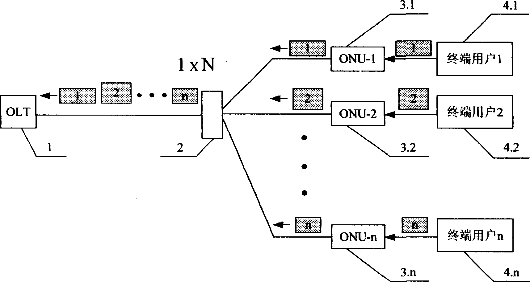
technical field [0001] The invention relates to a test technology of burst optical signal power of a passive optical network (hereinafter referred to as PON) system constructed in FTTX (fiber-to-the-home: FTTH; fiber-to-the-place: FTTP) network construction in optical communication. Background technique [0002] At present, FTTX network construction is becoming a hot spot of access network construction at home and abroad. Due to the use of passive optical network PON technology, FTTX enables multiple users to share a single optical fiber connection without using any active components, that is, components that generate and convert light through optoelectronic-optical (OEO) conversion. The architecture of the point greatly reduces the cost of network installation, management and maintenance. [0003] The new generation of network construction will inevitably bring new test problems, and new test methods are required. In the PON system, the optical power test of the uplink sig...

Claims


Application Information

Patent Timeline
Patent Type & Authority Applications(China)
IPC IPC(8): H04B10/12H04B10/075
Inventor 张建涛印新达
Owner GUANGXUN SCI & TECH WUHAN
Why Eureka
Try Eureka