Method of quench hardening and device for use therein

A technology of quenching device and quenching oil, which is applied in the direction of quenching device, furnace, heat treatment equipment, etc., can solve the problems of unbalanced heat treatment deformation and unbalanced flow rate, and achieve the goal of suppressing carburizing quality and unbalanced heat treatment deformation, and reducing cooling speed unbalanced, reducing the effect of unbalanced

Inactive Publication Date: 2006-12-27
KOYO THERMO SYST CO LTD
View PDF0 Cites 2 Cited by
  • Summary
  • Abstract
  • Description
  • Claims
  • Application Information

AI Technical Summary

Problems solved by technology

Therefore, in addition to the items to be processed, since the flow of the coolant is blocked by the trays and fixtures, the flow velocity is also uneven in the tray, which also becomes the cause of the uneven deformation of the heat treatment.

Method used


Image

  • Method of quench hardening and device for use therein
  • Method of quench hardening and device for use therein
  • Method of quench hardening and device for use therein

Examples


Embodiment Construction

[0026] Hereinafter, embodiments of the present invention will be described with reference to the drawings.

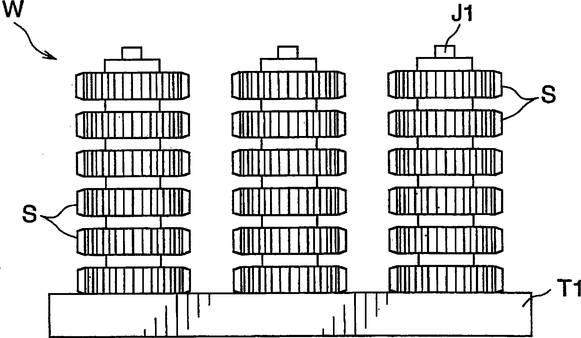
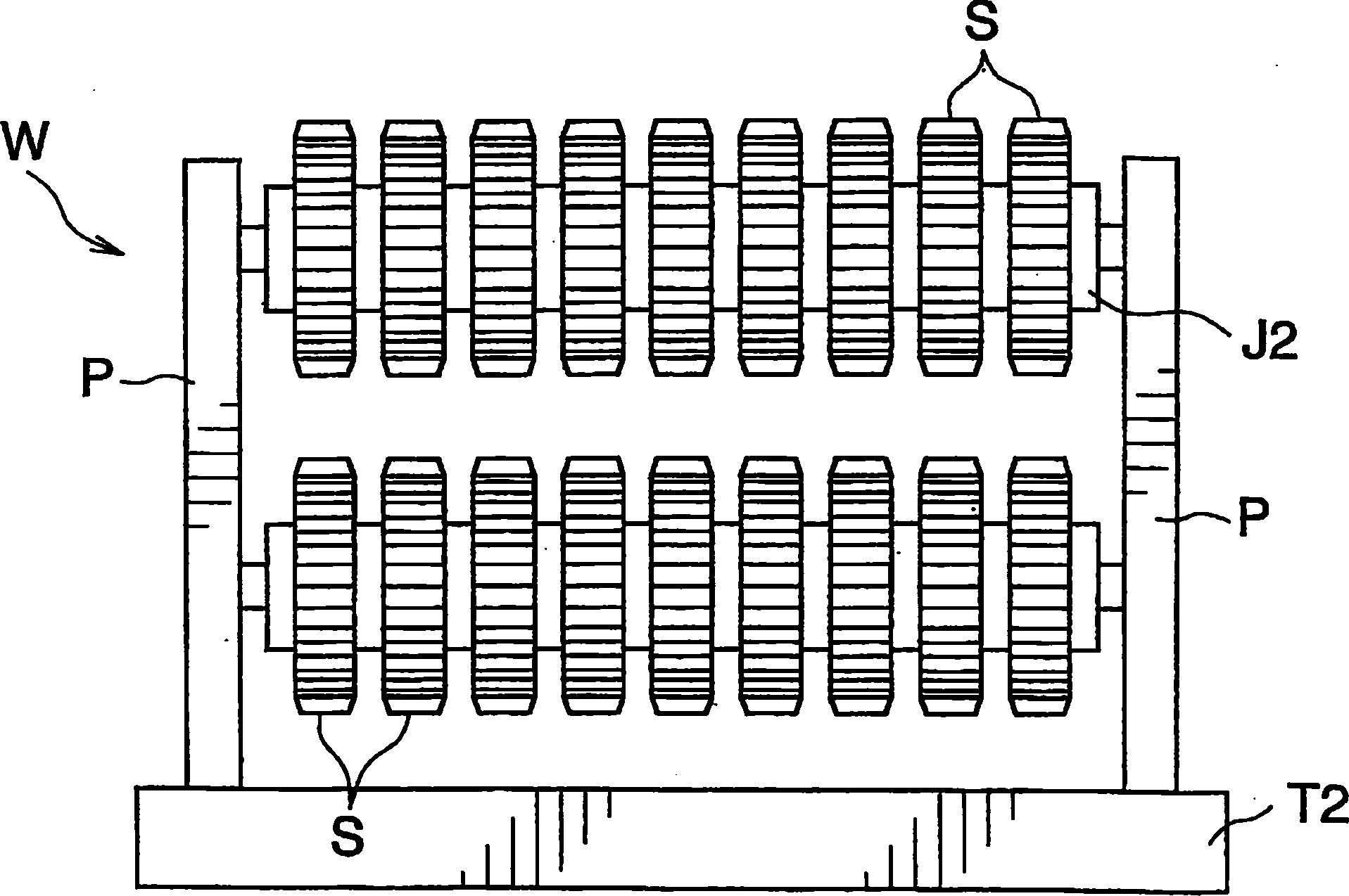
[0027] figure 1 and figure 2 It shows the arrangement of ring-shaped items S to be processed such as gears. figure 1 In , a plurality of vertical bar-shaped jigs J1 are erected on the upper surface of the tray T1 (also in the direction perpendicular to the paper surface). A plurality of items S to be processed are embedded at predetermined intervals on each jig J1. This state is called a flat arrangement. figure 2 Among them, a pair of piles P are erected at both ends of the upper surface of the tray T2, and the horizontal bar-shaped jig J2 is set up on the two piles P and fixed (in the direction perpendicular to the paper surface) with a distance between the upper and lower sides. also available above). A plurality of items S to be processed are embedded at predetermined intervals on each jig J2. This state is called a sideways placement.

[0028] In the case ...


PUM


Abstract

A method of quench hardening that in order to reduce fluctuation of the cooling rate of coolant for treatment subject (S) and to inhibit fluctuations of carburized product quality and heat treatment strain, comprises agitating quenching oil (O) in oil bath (11) to thereby uniformalize the oil temperature, discontinuing the agitation, and immersing treatment subject (S) in the quenching oil (O) of the oil bath (11) wherein the treatment subject (S) is oscillated in the longitudinal and / or lateral direction with a cycle of 2 to 10 sec.

Description

technical field [0001] The present invention relates to a quenching method for carburizing and quenching iron and steel parts such as gears and bearings, and a quenching device using the method. Background technique [0002] In the past, the known quenching device has: an oil tank, which is used to fill the coolant; and a stirrer, which stirs the coolant to make the coolant in the oil tank flow upward. [0003] For the coolant, you can choose the appropriate oil type and the appropriate oil temperature according to the quality, shape, hardenability, etc. of the steel parts. In addition, the cooling capacity can be adjusted by stirring at an appropriate flow rate. [0004] In the case of immersing the object to be treated in the stirred coolant, the cooling speed of the object to be treated on the front side directly impacted by the flow of the coolant and the back side on the opposite side thereof are unbalanced, and as a result, this becomes a source of leakage. Carbon qu...

Claims


Application Information

Patent Timeline
Patent Type & Authority Applications(China)
IPC IPC(8): C21D1/18C21D1/63C21D9/32
CPCC21D1/18C21D9/32
Inventor 松原周桥本弘之山口和嘉山村典
Owner KOYO THERMO SYST CO LTD
Why Eureka
Try Eureka