Electric pneumatic adjustable flexible polishing tool
A flexible polishing and adjustable technology, which is applied in the direction of polishing machine tools, manufacturing tools, wheels with flexible working parts, etc., can solve the problems of difficult to achieve precise correction of local shape and surface, inability to control online, and low polishing efficiency. Achieve the effect of stable and uniform normal polishing force, precise correction and high polishing efficiency
- Summary
- Abstract
- Description
- Claims
- Application Information
AI Technical Summary
Problems solved by technology
Method used
Image
Examples
Embodiment 1
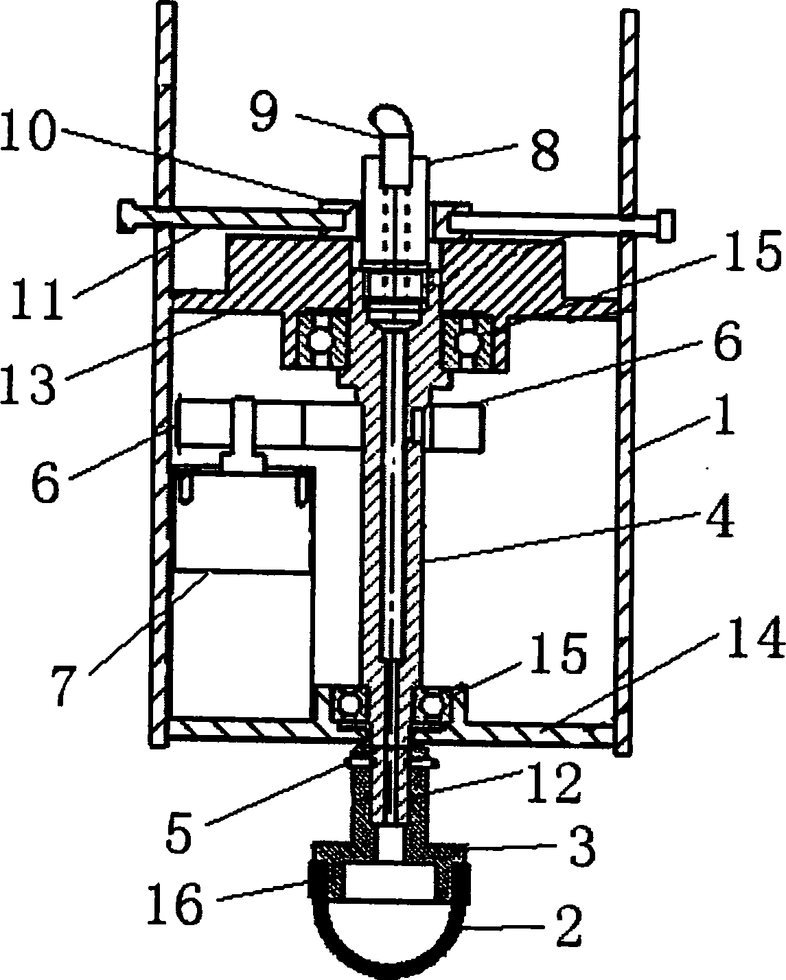
[0026] refer to figure 1 , an electric pneumatic adjustable flexible polishing tool, comprising a bracket 1, an air bag 2, a polishing cloth at the front end of the air bag 2 as a working surface, and the air bag 2 is installed on the air bag holder 3;
[0027] The airbag holder 3 is installed on the front part of a rotating shaft 4, and the airbag 2 is fixed by the airbag fixing ring 16. The airbag holder 3 is connected to the rotating shaft 4 through a key and a tightening screw 5. The key connection controls the circumferential positioning, and the tightening screw 5 controls the axial positioning and additional circumferential positioning. The rotating shaft 4 is connected to a gear 6 through a gear 6. The output shaft connection of the motor 7;
[0028] The rear end of the rotating shaft 4 is connected to a rotary air intake joint 8, the front of the rotary air intake joint can rotate with the rotating shaft, the rear of the rotary air intake joint 8 is connected to the ...
Embodiment 2
[0032] refer to figure 1 , the airbag holder 3 is installed with a sealing ring 12 to ensure the sealing effect so that the airflow does not leak out. The rest of the structure and implementation are the same as in Embodiment 1.
Embodiment 3
[0034] refer to figure 1 , the electric pneumatic adjustable flexible polishing tool also includes an upper support plate 13 for supporting the V-shaped block 10, a lower support plate 14 for supporting the motor 7, the upper support plate 13 and the lower support plate The supporting plates 14 are connected with the rotating shaft 4 through bearings 15 . The V-shaped block 10 is supported by the upper support plate 13, and the motor 7 is supported by the lower support plate 14, so that the stability of the whole mechanism is better. The rest of the structures and implementations are the same as in Embodiment 2.
PUM
 Abstract
Description
Claims
Application Information
 - R&D Engineer
- R&D Manager
- IP Professional
- Industry Leading Data Capabilities
- Powerful AI technology
- Patent DNA Extraction
Browse by: Latest US Patents, China's latest patents, Technical Efficacy Thesaurus, Application Domain, Technology Topic, Popular Technical Reports.
© 2024 PatSnap. All rights reserved.Legal|Privacy policy|Modern Slavery Act Transparency Statement|Sitemap|About US| Contact US: help@patsnap.com


