Photomask used for color filter technology

A color filter and photomask technology, applied in the field of photomasks, can solve the problems of high repeatability, manufacturing cost, waste of labor, offset and the like

Inactive Publication Date: 2006-12-13
AU OPTRONICS CORP
View PDF0 Cites 0 Cited by
  • Summary
  • Abstract
  • Description
  • Claims
  • Application Information

AI Technical Summary

Problems solved by technology

On-site operators obtain the photomask with alignment marks and expose the color filter; in terms of this highly repeatable and technically uncomplicated step, on-site operators usually work at a lower standard For the exposure procedure, if the alignment mark "BGR" is taken as an example, on the same plane, the on-site operator is very likely to invert the photomask 10 by 180 degrees, and the result will be as follows image 3 shown
It can be seen from the figure that even if the photomask is inverted, the second scanner at the fixed position will still display the word "G". (Especially under long hours of work and heavy workload) It is very difficult to identify the difference between the front and back of the font, detect the error, and correct it immediately; the operator seems to have a mistake in the correct position of the photomask 10 It will cause subsequent operators to mistakenly think that it is correct to carry out subsequent exposure procedures, resulting in wrong lithography results
[0006] Furthermore, the undetected photomask inversion in the above-mentioned production line actually comes from the fact that the operator only observes the same words through the scanner, which is judged to be correct alignment, although the exposure The program will not be hindered, but in fact, the pixel pattern (pixel pattern) has been seriously shifted from the original expected position due to the inversion of the corresponding exposure position, making the exposed product completely unusable
What's more, because the photomask inversion phenomenon is not easy to detect in the process, it is possible to continue the production and manufacture until a certain inspection station, or even until the final product is obtained, the product defect is not found. and a serious waste of manpower

Method used


Image

  • Photomask used for color filter technology
  • Photomask used for color filter technology
  • Photomask used for color filter technology

Examples


Embodiment Construction

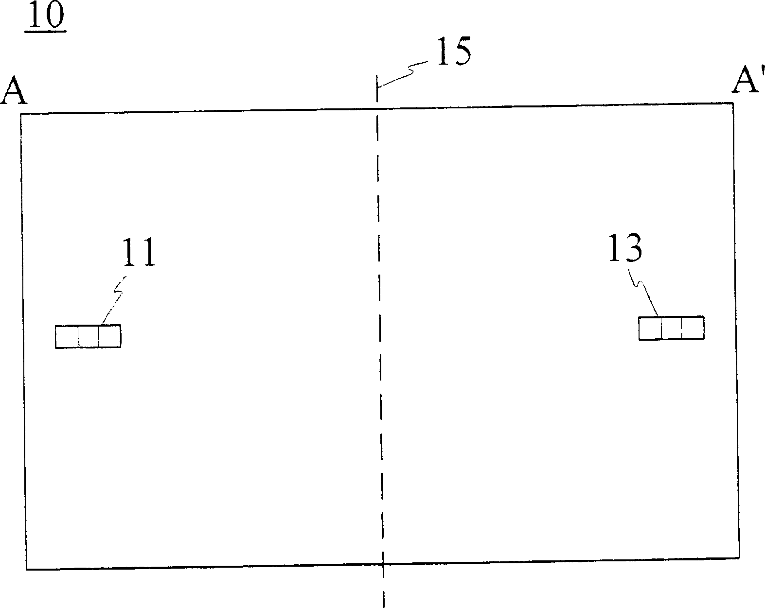
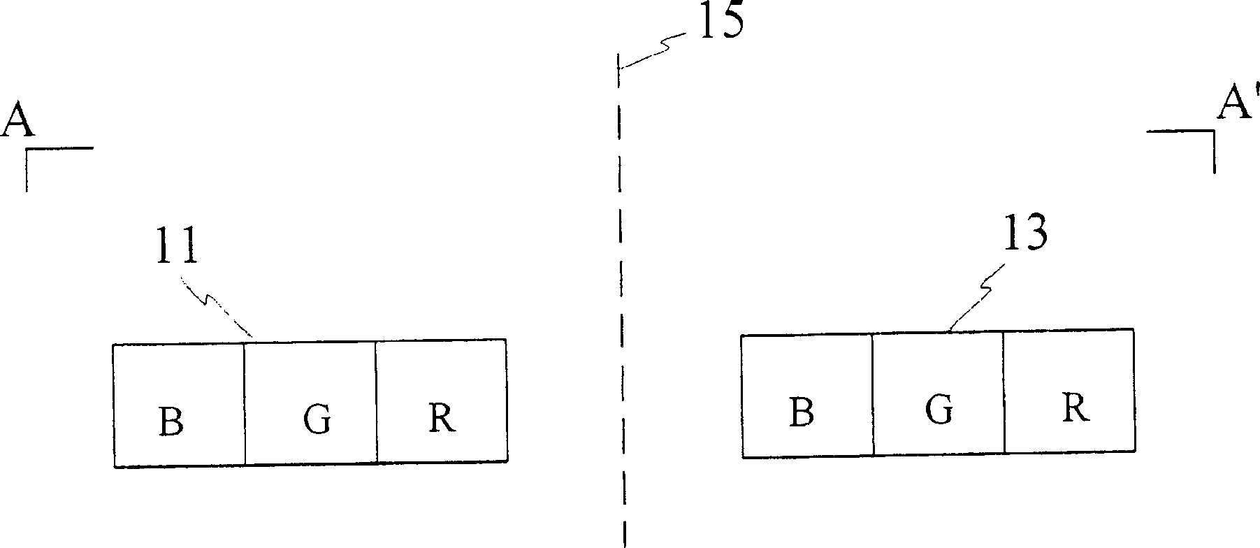
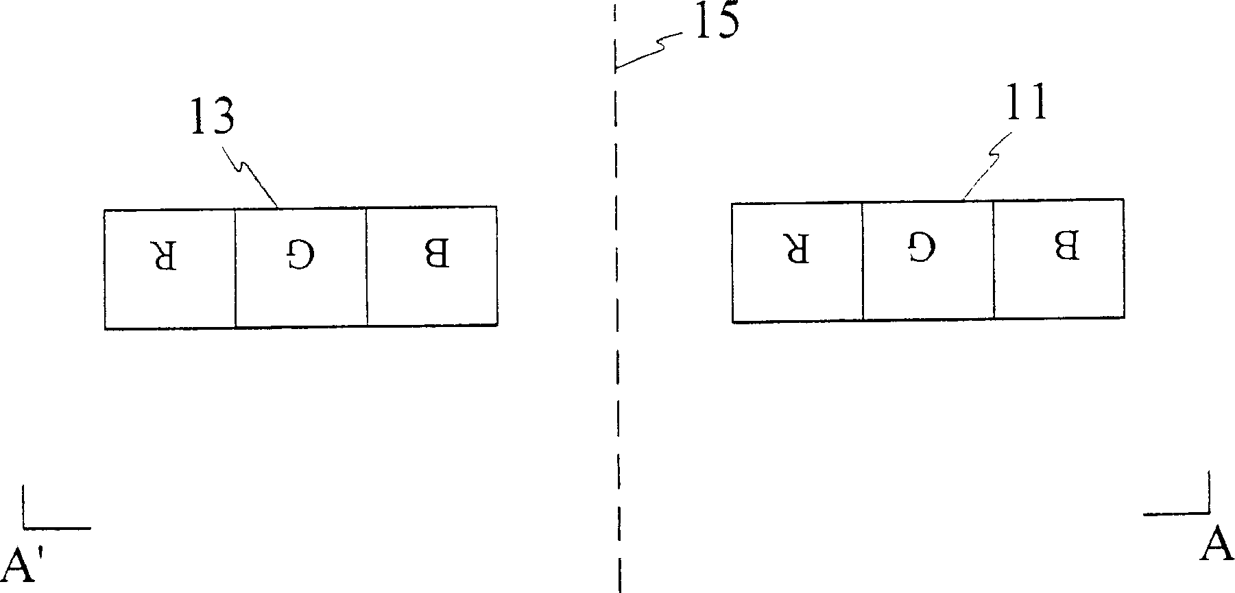
[0039] The first embodiment of the present invention is as Figure 4 As shown, a photomask 30 for color filter process is disclosed. A reference symmetry axis 40 is set on the photomask 30. The symmetry axis can be an actual symmetry axis or a virtual reference symmetry axis 40; It has a center of symmetry 41 . The photomask 30 further includes a first alignment mark 31 and a second alignment mark 31', which are substantially symmetrical to each other with respect to the reference axis of symmetry 40 and the center of symmetry 41. In this embodiment, the first alignment mark 31 and the second alignment mark 31 are preferably substantially horizontally symmetrical with respect to the reference axis of symmetry 40 .

[0040] It should be noted that, the first alignment mark 31 and the second alignment mark 31' in this embodiment are not limited to horizontal symmetry, but can also be substantially obliquely symmetrical (not shown). Furthermore, as long as the first alignment m...


PUM


Abstract

The invention discloses a photo mask which comprises a first pair of site marks set symmetrically and a second pair of site marks. The first and second pairs of marks have plural different graphs, but the graphs of the first and the second pairs of marks are corresponding to each other, and the corresponding graphs have actual asymmetrical distances to the photo mask reference symmetrical center; when the photo masks on the same plane, after rotating 180 degree, different graphs corresponds to the same site, which make it easy to identify that the photo mask is placed in wrong direction and to modify.

Description

technical field [0001] The invention relates to a photomask used in the color filter process, in particular to a photomask with alignment marks used in the color filter process. Background technique [0002] Liquid crystal display has the advantages of power saving, light weight, low radiation and easy to carry. It has become the mainstream product on the market and is widely used in TVs, computer screens, notebook computers, car navigation systems, mobile communication devices, etc., gradually replacing traditional display. One of the key components is the color filter. [0003] Generally speaking, the color filter adopts a proximity exposure process in a photolithography process. Currently, leading manufacturers using proximity exposure machines include Topcon, Seiko, Hitachi DECO, Orc Manufacturing and DNS. In the photolithography process, in order to ensure that the exposure position of the substrate under the photomask is correct, a plurality of detection points for ...

Claims


Application Information

Patent Timeline
Patent Type & Authority Applications(China)
IPC IPC(8): G03F1/14G02B5/23G03F1/42
Inventor 吴佳恩黄淑仪乐瑞仁
Owner AU OPTRONICS CORP
Why Eureka
Try Eureka