
Reflective type silicon-based liquid crystal microdisplay optical engine

A silicon-based liquid crystal, optical engine technology, applied in optics, optical components, instruments, etc., can solve the problems of low contrast, low color image resolution, poor clarity, etc., to achieve aberration balance, complete optical path balance, Guarantee the effect of accurate coincidence

Inactive Publication Date: 2006-12-13
WUHAN ZHONGYUAN ELECTRONICS GRP
View PDF4 Cites 0 Cited by
  • Summary
  • Abstract
  • Description
  • Claims
  • Application Information

AI Technical Summary

Problems solved by technology

However, in the existing dichroic light splitting / combining mirrors, only the substrate glass
This brings about two important problems: one is that the light will produce parallel lateral displacement when it passes through the parallel plane glass plate installed obliquely (only normal incidence will not cause lateral displacement), if it is divergent light or convergent light (this is The imaging optical path that is often used), the lateral displacement and the angle are linear in the small angle range, and the lateral displacement and the angle are nonlinear in the large angle range
Therefore, for the optical engines involved in the above documents, there are still disadvantages such as low resolution of color images, poor definition, low contrast, etc.

Method used


Image

  • Reflective type silicon-based liquid crystal microdisplay optical engine
  • Reflective type silicon-based liquid crystal microdisplay optical engine
  • Reflective type silicon-based liquid crystal microdisplay optical engine

Examples


Embodiment Construction

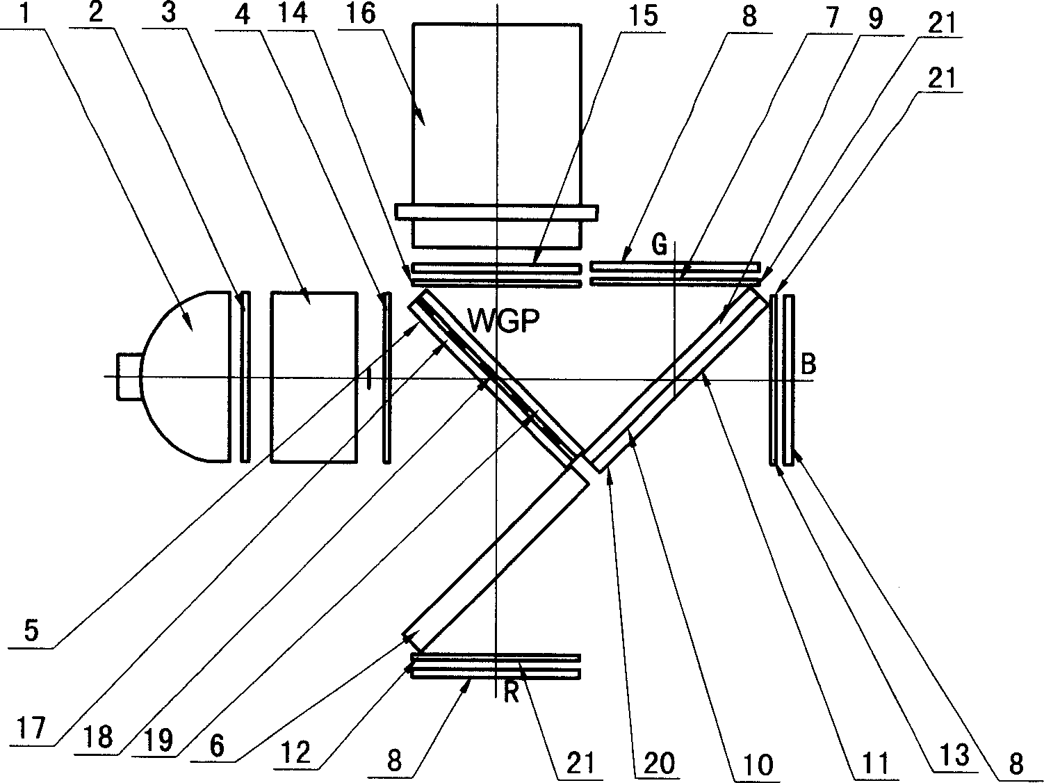
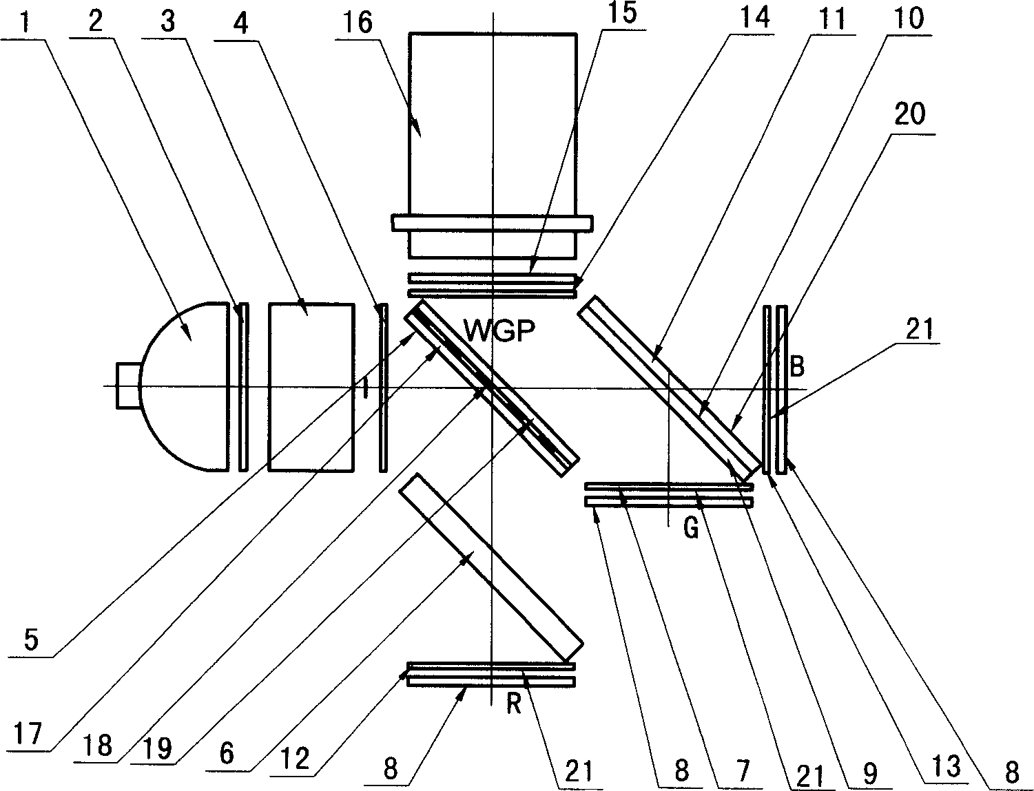
[0043] Figure 1a, Figure 1b to Figure 12a , Figure 12b All are specific implementation examples of the present invention. From Figure 1a to Figure 12b It can be seen that: the present invention is all composed of light source 1, polarizer 2, spotlighting assembly 3, the first color selection filter polarization conversion sheet 4, metal wire grid polarization splitting / combining mirror (WGP) 5, compensation plate 6, Green (G) color broadband λ / 4 wave plate 7, liquid crystal on silicon (Lcos) chip 8, dichroic splitting / combining mirror 20 (substrate glass plate 9, dichroic splitting / combining film 10, protective glass plate 11 ), red (R) color broadband λ / 4 wave plate 12, blue (B) color broadband λ / 4 wave plate 13, the II color selection filter polarization conversion sheet 14, polarizer 15 and projection lens 16 constitute. And it is assumed that the light emitted from the light source 1 through the polarizer 2 and the spot lighting assembly 3 from FIG. 1a to FIG. 6b is ...


PUM


Abstract

The invention provides a micro display optical engine which comprises a light source, a polarizer, light gathering illuminating components, a first and second filter polarizer converting slices, metal grating polarizing separating / merging lens, a compensating glass board, two-color separating / merging lens, a wide-bandlambada / 4 wave slice, a silicon base liquid crystal chip, a detecting polarizer and a projecting lens. Wherein the two-color separating / merging lens includes base glass board, two-color separating / merging light film and a protecting glass board; the wide-band lambada / 4 wave slice includes red, green and blue three color wide-bandlambada / 4 wave slices. The invention increases a protecting glass board based on the dual way two-color separating / merging lens to ensure the light paths balance of the red, green and blue imaging light channels.

Description

technical field [0001] The invention provides a reflective silicon-based liquid crystal micro-display optical engine, precisely, it is an optical path for realizing red (R), green (G) and blue (B) three-way imaging light channels in a glass medium Completely balanced, it can achieve the best correction of aberrations, and the lateral image movement generated by the three imaging optical channels on the imaging surface is completely synchronized, thus ensuring the red (R), green (G) and blue (B) three primary color image images The invention relates to an optical engine technical scheme for obtaining high-definition color images by accurately overlapping pixels, and belongs to the field of micro-display technology. Background technique [0002] At present, the development trend of digital display technology is based on the premise of high-definition and large-screen display. Compared with other flat panel display technologies, the liquid crystal-on-silicon (Lcos) micro-displ...

Claims


Application Information

Patent Timeline
Patent Type & Authority Applications(China)
IPC IPC(8): G02B27/10G02B27/28
Inventor 刘明华张红波
Owner WUHAN ZHONGYUAN ELECTRONICS GRP
Learn More