
Printing solder detecting device

A technology of inspection device and soldering, which is applied in the direction of measuring device, assembling printed circuit with optical device and electrical components to achieve the effect of shortening time

Inactive Publication Date: 2006-12-13
ANRITSU CORP
View PDF1 Cites 10 Cited by
  • Summary
  • Abstract
  • Description
  • Claims
  • Application Information

AI Technical Summary

Problems solved by technology

Therefore, when there are many types of substrates and solder shapes to be judged, or even when there are many items to be judged, it takes considerable time and experience to find the reference value (allowable value).

Method used


Image

  • Printing solder detecting device
  • Printing solder detecting device
  • Printing solder detecting device

Examples


Embodiment Construction

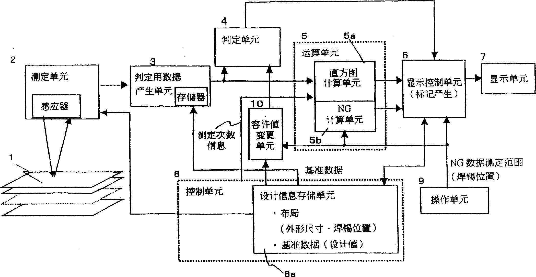
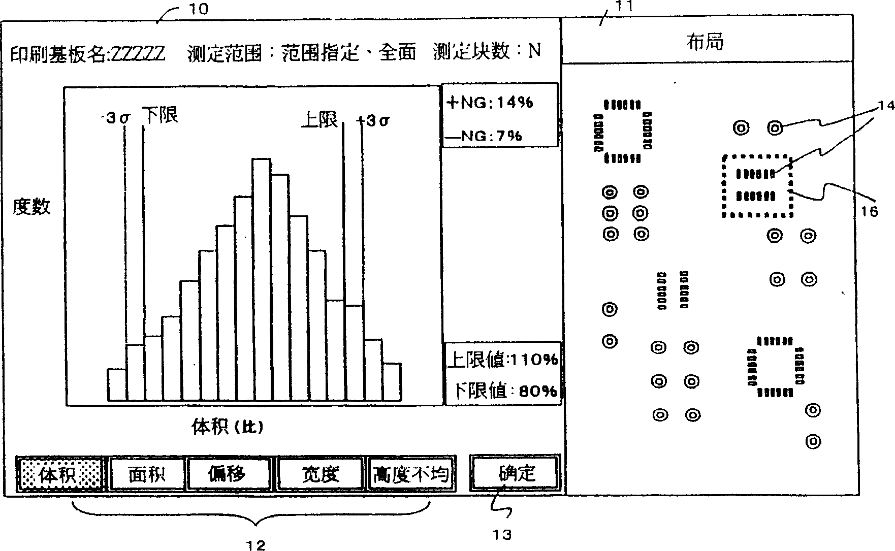
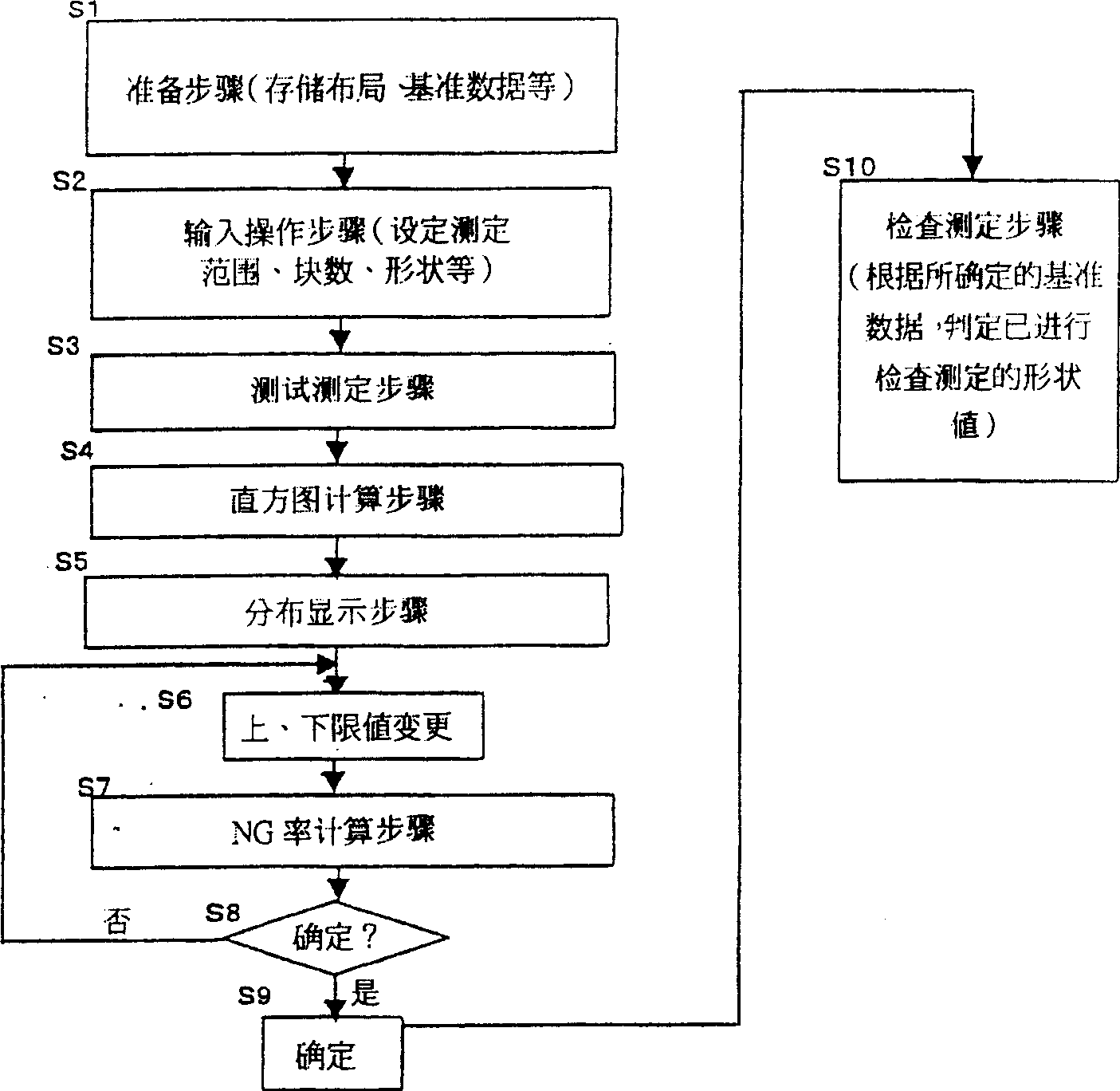
[0065] Embodiments of the present invention will be described using the drawings. figure 1 It is a functional block diagram showing the configuration of the embodiment of the present invention. figure 2 for figure 1 The display example of this embodiment is a display example of the NG rate and order distribution when the measurement range and shape are designated. image 3 to represent figure 1 The figure of the operation flow of this embodiment. Figure 4 for with image 3 A diagram of the different action flows of the usage operation. Figure 5 to express with figure 1 Functional block diagrams of the configurations of other embodiments corresponding to the embodiment of the present invention. Figure 6 to represent Figure 5 A diagram of an operation flow in another embodiment in . Figure 7 to represent Figure 5 Figures showing examples in other embodiments.

[0066] figure 1 In the measurement unit 2, there is a moving mechanism part (not shown), which receiv...


PUM


Abstract

The invention provides the technology of judging quantity when displaying solder form distribution, easily designing reference value. The invention uses measuring unit (2) to measure soldering state, according the measured value, uses the histogram calculation unit (5a) to calculate frequency distribution of form value, uses display controlling unit (6) to display the frequency distribution on the display unit (7), and uses recognizable pattern to display variable input distribution range. The NG calculation unit (5b) calculates the fraction defective or percent of pass, and defines the expected distribution range.

Description

technical field [0001] The present invention relates to a printed solder inspection device for measuring and inspecting the state of solder formation when cream-like solder is printed on a printed circuit board (Print Circuit Board) used for surface mount electronic parts and the like. In particular, it relates to a technology that facilitates the setting of standards for good / failure judgment. Background technique [0002] Conventionally, printed solder inspection equipment includes a sensor that irradiates laser light or the like to the surface of a substrate (hereinafter referred to simply as a "board") and receives reflected light emitted from the surface of the substrate. measurement (triangulation)), for example, measured values ​​of displacement (including height) or luminance (including the amount of light reflected from the substrate and the amount of received light (intensity of light)) of the printed solder position on the substrate, and The reference data servin...

Claims


Application Information

Patent Timeline
Patent Type & Authority Applications(China)
IPC IPC(8): G01B11/02G01B11/24H05K3/34
CPCG01N21/956G06T7/0004G06T2207/30152
Inventor 木村刚辻村映治
Owner ANRITSU CORP
Learn More