
Splicing device, yarn splicing method and joint

A technology of splicing device and yarn, applied in the direction of piecing device, spinning machine, transportation and packaging, etc., can solve problems such as appearance deterioration, and achieve the effect of reducing manufacturing cost and simplifying shape

Inactive Publication Date: 2006-12-13
MURATA MASCH LTD
View PDF1 Cites 10 Cited by
  • Summary
  • Abstract
  • Description
  • Claims
  • Application Information

AI Technical Summary

Problems solved by technology

In other words, when trying to increase the strength at the joint, the intersection C becomes conspicuous, thus deteriorating the appearance

Method used


Image

  • Splicing device, yarn splicing method and joint
  • Splicing device, yarn splicing method and joint
  • Splicing device, yarn splicing method and joint

Examples


Embodiment Construction

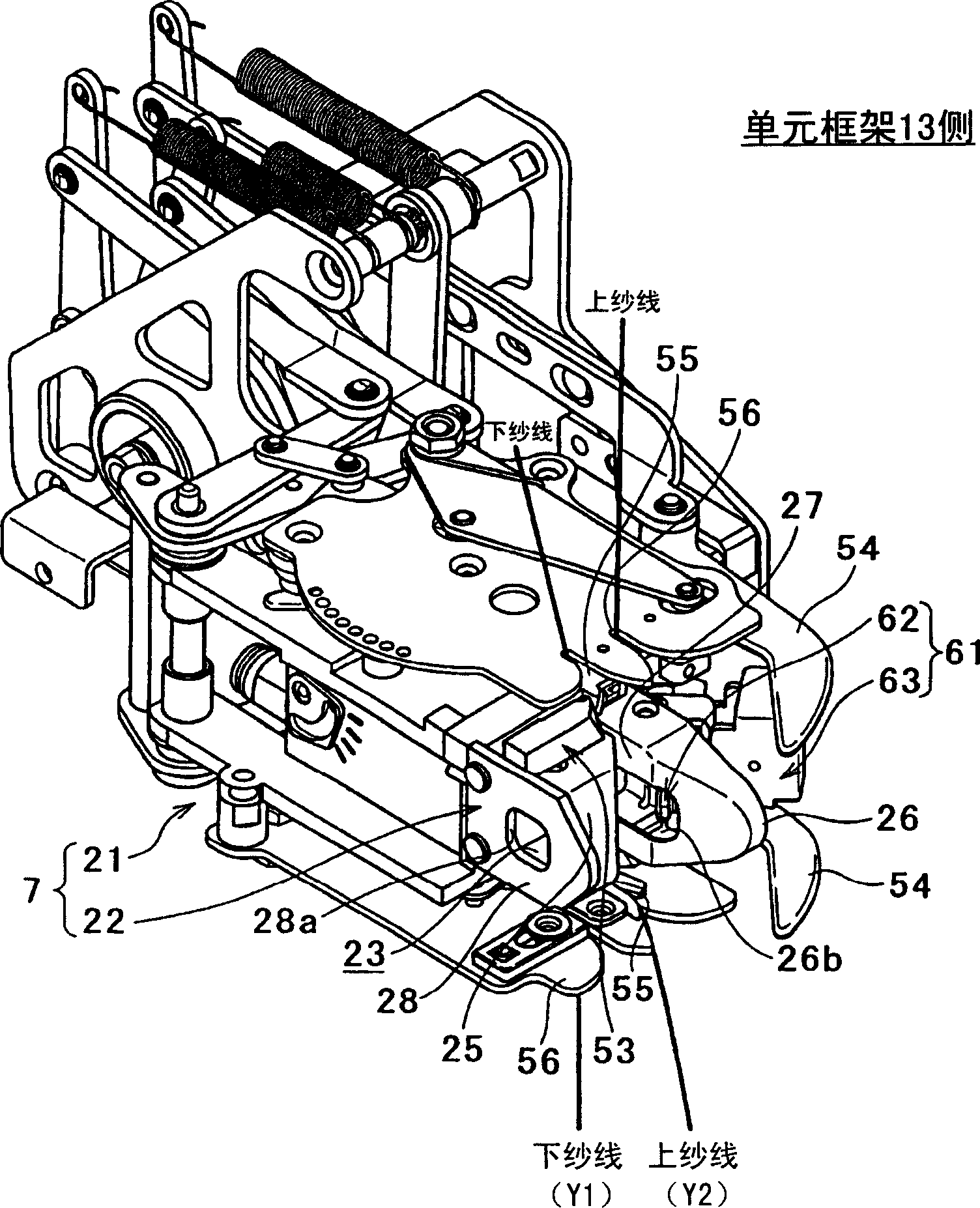
[0047] Next, an embodiment of the present invention will be described with reference to the drawings. First, see Figure 11 Describes an automatic winder incorporating a splicing device.

[0048] Figure 11 A schematic front view of an automatic winder is shown. The yarn winding unit 1 of the automatic winder winds the spun yarn Y (flax yarn in this embodiment) unwound and supplied from the yarn supply bobbin B under the traversing action of the traversing drum 3 . A take-up bobbin P having a predetermined length and a predetermined shape is formed on the take-up bobbin tube Bf. exist Figure 11 In, only one yarn winding unit 1 is shown, however, a plurality of such yarn winding units 1 are installed side by side, and an unshown frame control device is arranged at one end of the installation direction, in this In this case, a yarn winder (automatic winder) has been constructed.

[0049] In the yarn winding unit 1, a unit frame 13 is provided on a horizontal side of the y...


PUM


Abstract

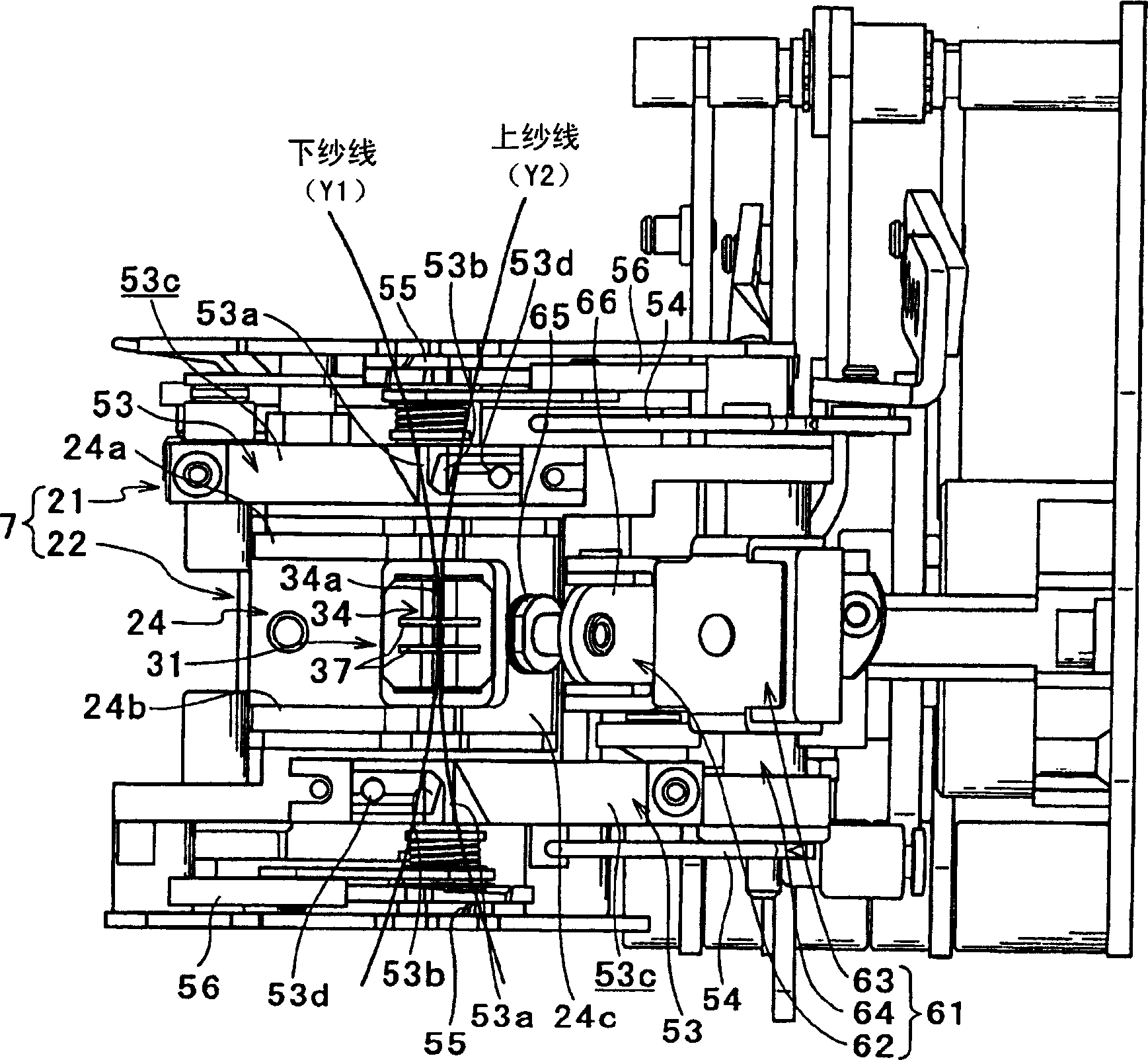
A twisting member (31) of a splicing device includes a yarn splicing hole (34a) in which yarns to be twisted (Y, Y1, Y2) are set, groove portions (37, 37) as gas release portions (37, 37) formed in directions different from a longitudinal direction of the yarn splicing hole (34a), and air paths (34c, 34c) provided in a pair that form air injection ports (34b, 34b), respectively, in the yarn splicing hole (34a) and form whirling flows opposite to each other inside the yarn splicing hole (34a). A plurality of groove portions (37, 37) are formed, and the air injection ports (34b, 34b) formed by the air paths (34c, 34c) in the yarn splicing hole (34a) are positioned further outside than the plurality of groove portions (37, 37).

Description

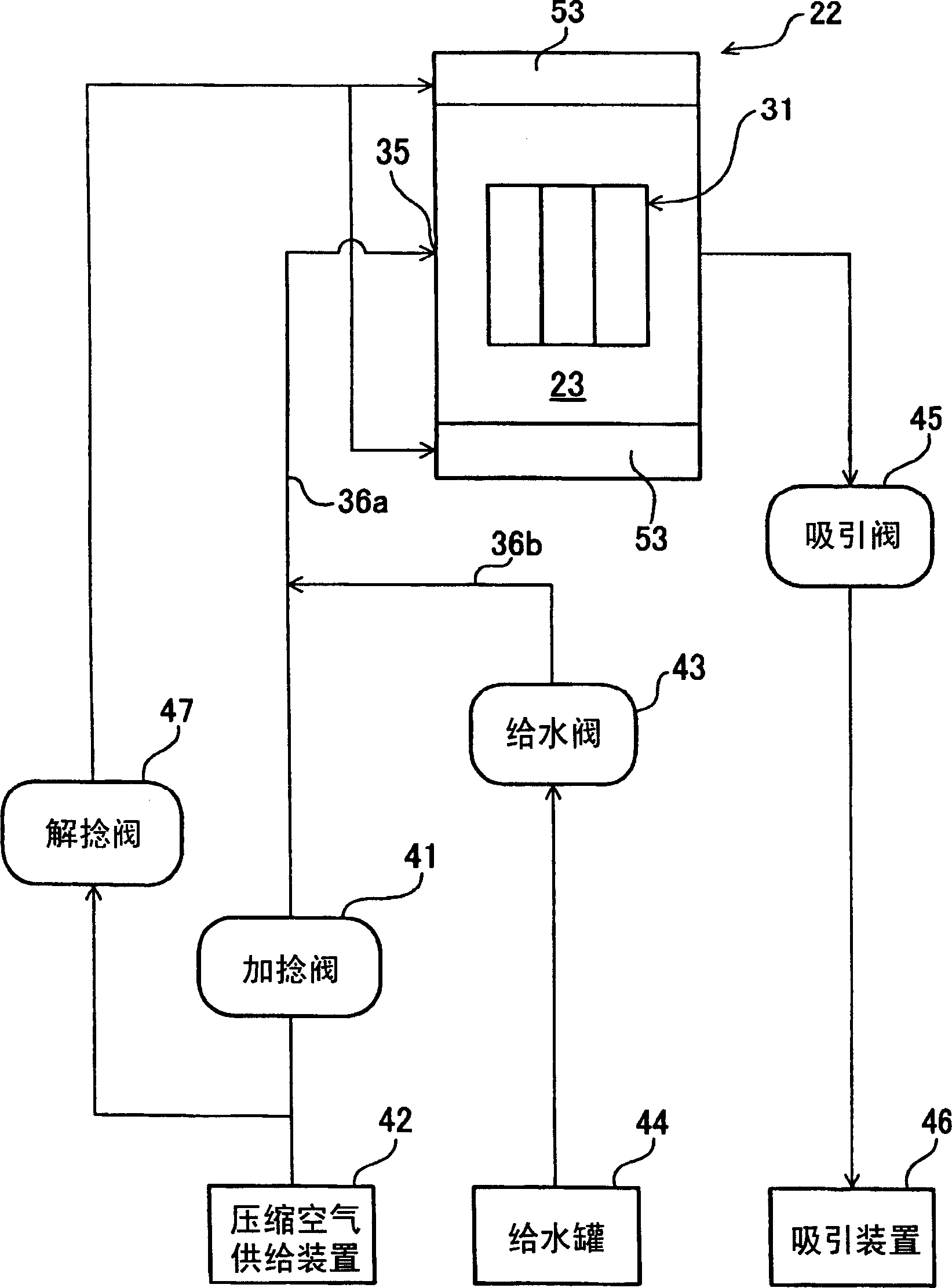
technical field [0001] The present invention mainly relates to a splicing device which applies a fluid such as compressed air to yarn ends in the untwisting direction and overlaps said yarn ends with each other and applies a fluid such as compressed air to said overlapping portions , to splice the yarn. Background technique [0002] Such a splicing device is disclosed in Japanese Patent Application Laid-Open No. 2005-113314 (Document 1) previously submitted to the Japan Patent Office (JPO) by the applicant of the present invention. The splicing device in Document 1 has a twisting element that jets compressed air to which liquid is added to twist (splice) yarn ends. Thus, depending on the type of yarn, yarn splicing quality, appearance and yarn strength can be improved. [0003] as document 1 Figure 10 As shown, the twisting element includes a yarn splicing hole, an air injection port and a slit-like groove, the yarn to be twisted is set in the yarn splicing hole, and the ...

Claims


Application Information

Patent Timeline
IPC IPC(8): B65H69/06D01H15/00
CPCB65H2701/31B65H69/061B65H69/063
Inventor 田村武士
Owner MURATA MASCH LTD
Learn More