
Backlight unit and liquid crystal display

A technology of backlight module and liquid crystal panel, which can be used in instruments, optics, nonlinear optics, etc., and can solve problems such as difficult balance.

Active Publication Date: 2006-11-29
AU OPTRONICS CORP
View PDF0 Cites 5 Cited by
  • Summary
  • Abstract
  • Description
  • Claims
  • Application Information

AI Technical Summary

Problems solved by technology

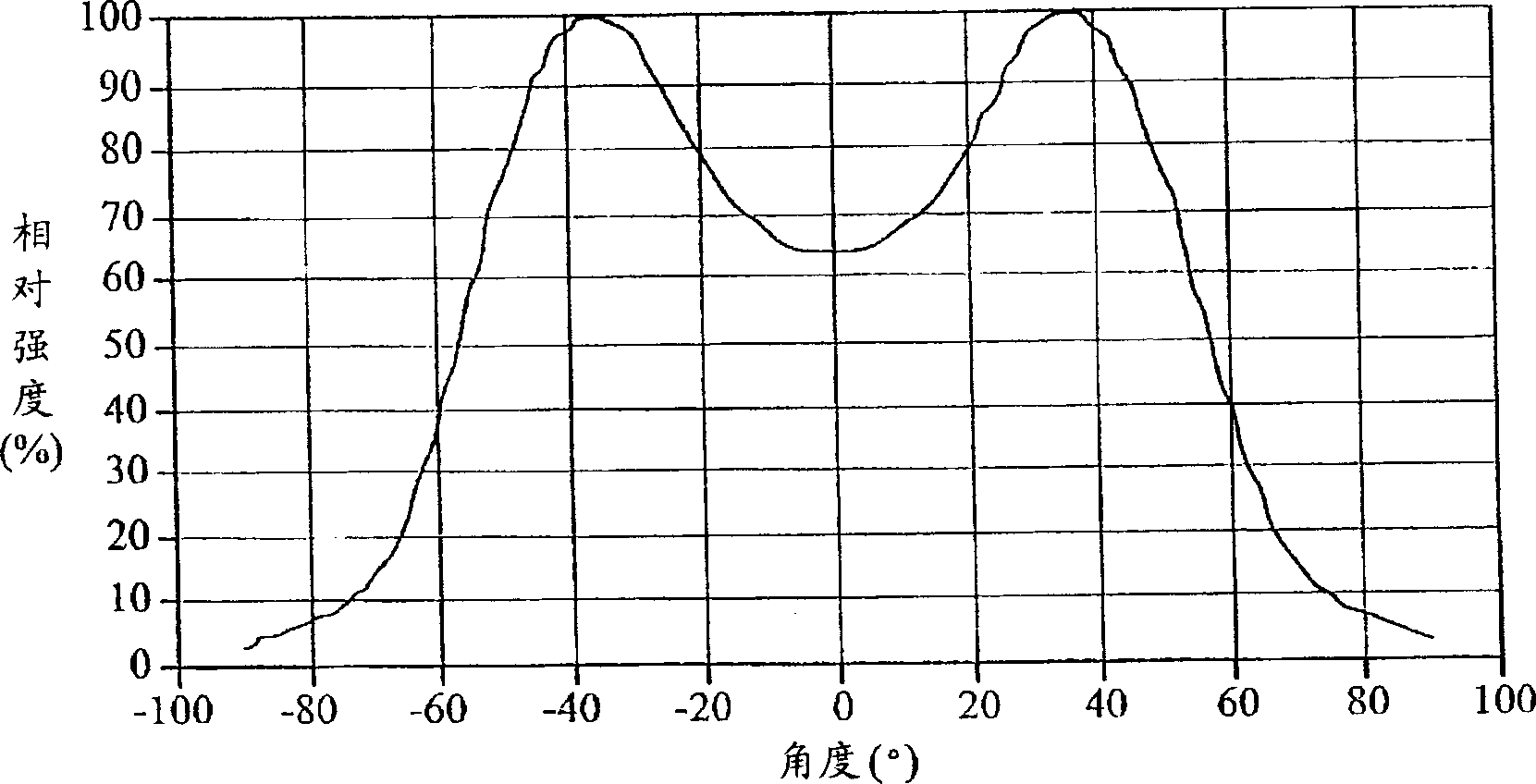
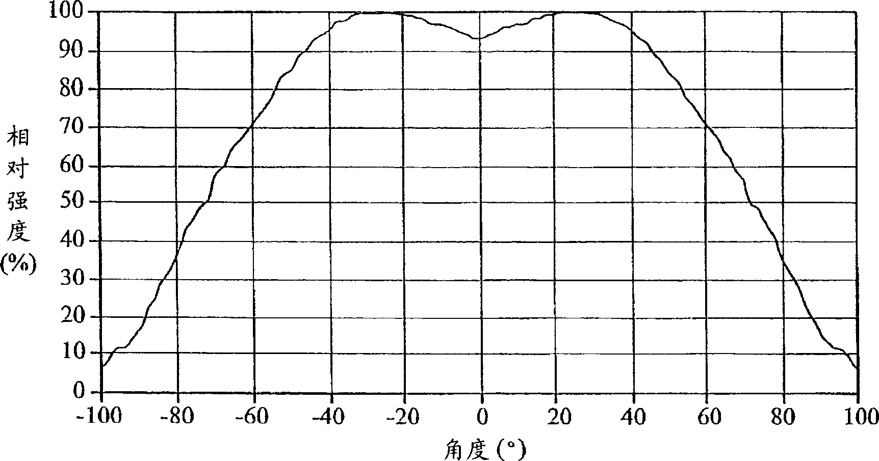
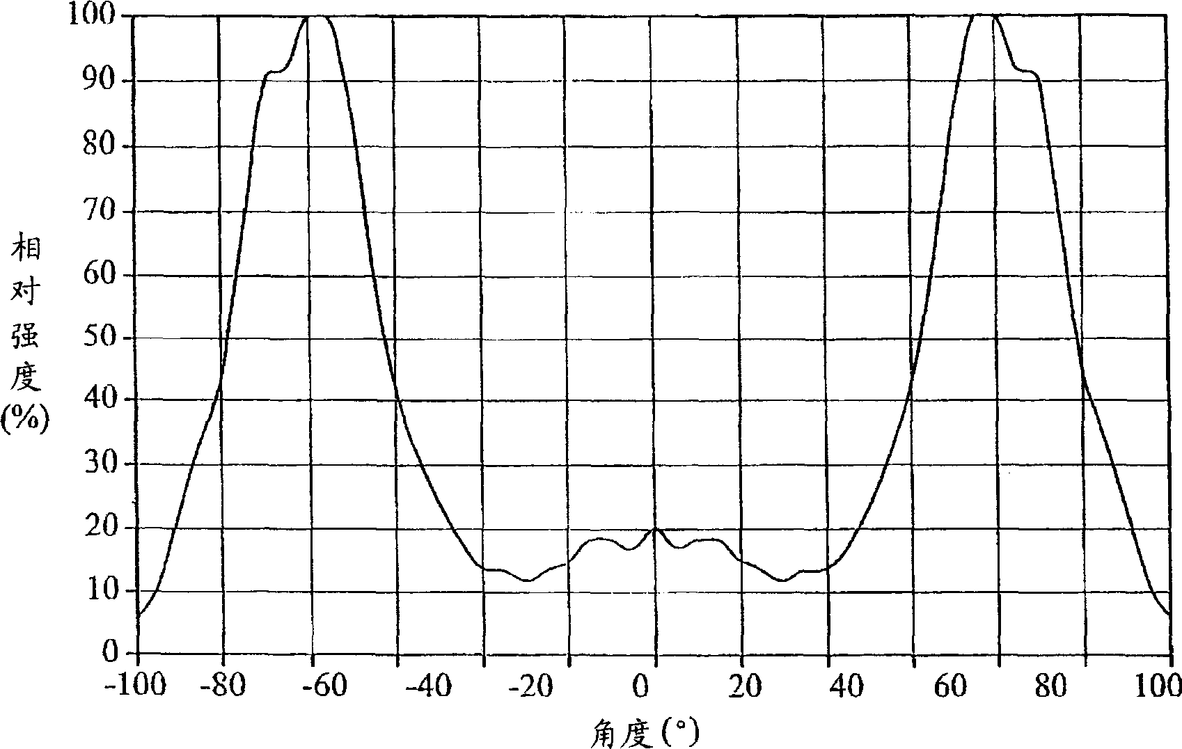
However, under the current structure, the central brightness and uniformity are determined according to the distribution of LEDs on the XY plane, which are mutually exclusive parameters, and it is often difficult to achieve a further balance in practice

Method used


Image

  • Backlight unit and liquid crystal display
  • Backlight unit and liquid crystal display
  • Backlight unit and liquid crystal display

Examples


Embodiment Construction

[0043] See figure 2 , which shows an exploded schematic diagram of a flat panel display device. This display device is generally composed of a backlight module 1, a display panel 2 and a casing 3. For a detailed exploded perspective view of the backlight module 1, please refer to image 3 . The backlight module 1 is generally composed of a support base 10 , a light source 101 , a diffusion plate 11 , other optical components 12 and an outer frame 13 . The so-called other optical components 12 here can be one or more optical films, and the optical films can be, for example, diffusion sheets, prism sheets, microstructure sheets, enhancement sheets or other optical properties that can change the incident light. Diaphragm. In addition, between the support base 10 and the diffusion plate 11, if necessary, some optical components can also be added to improve the light utilization rate or meet the light distribution requirements; or add some auxiliary components to strengthen the...


PUM


Abstract

A backlight unit is prepared as setting a light source support zone on support base and at least two point light sources on light source support zone, setting diffusion plate above support base and two said point light sources, making positions of two said point light sources be different along thickness direction of backlight unit or making optical axis pointing directions of emitting light be different for raising optical performance of backlight unit.

Description

technical field [0001] The present invention relates to a backlight module, and in particular to a backlight module applicable to a liquid crystal display. Background technique [0002] In recent years, since the luminous efficiency of light-emitting diodes (LEDs) has been greatly improved, it is expected to keep pace with or even surpass cold-cathode fluorescent lamps (CCFLs) in the future, so light-emitting diodes (LEDs) will be more widely used in Various lighting equipment, especially suitable for light sources of various information display devices that require higher luminous quality and efficiency. [0003] Traditional fluorescent lamps are linear light sources, such as cold cathode fluorescent lamps (CCFL), which do not have a special optical axis and a special light pattern. When using these traditional light sources, there are not many design variables that need to be considered, which is relatively simple. However, for point light sources such as LEDs, the light ...

Claims


Application Information

Patent Timeline
IPC IPC(8): G02F1/13357G02F1/1335
Inventor 萧孟佳陈志光黄国栋许玉燕
Owner AU OPTRONICS CORP
Learn More