
Double-induction resistivity measuring instrument during drilling

A technology of inductive resistance and measuring instrument, which is used in surveying, earthwork drilling, wellbore/well components, etc. question

Active Publication Date: 2006-11-29
中石化石油工程技术服务有限公司 +3
View PDF0 Cites 34 Cited by
  • Summary
  • Abstract
  • Description
  • Claims
  • Application Information

AI Technical Summary

Problems solved by technology

[0004] This kind of instrument has the following disadvantages: Lateral resistivity logging belongs to the direct current logging method, and a power supply electrode is used to guide the direct current into the formation, and then a measuring electrode is used to measure the potential of a certain point in the well, only when there is conductive mud in the well. This method can only be used when the current channel
[0010] The instrument uses a coil system consisting of a transmitting coil and two receiving coils with a single fixed detection depth, which can only provide formation resistivity at a radial detection depth, and cannot be used to explain complex invasion profiles and divide permeable layers
For the permeable layer, mud invasion causes the resistivity to change in the radial direction. Since only one resistivity value at the radial detection depth can be obtained at the same depth point, it cannot be used to explain the formation invasion status, and it is impossible to determine the degree of mud invasion of the formation. conditions and reservoir permeability, which is not conducive to the interpretation of oil and gas layers, so that it cannot be used to accurately measure the true resistivity of the formation
In addition, different types of mud invasion and resistivities at different radial detection depths have different characteristics of oil, gas and water layers. The difference characteristics shown can identify oil and gas, so multi-depth resistivity measurement is very important for LWD tools, but this tool cannot meet this requirement, because its coil system design structure is fixed, each coil system Only one depth of resistivity can be provided. To obtain the resistivity of different detection depths, it is necessary to use different coil systems for multiple measurements. This method is difficult to achieve in practical engineering applications.

Method used


Image

  • Double-induction resistivity measuring instrument during drilling
  • Double-induction resistivity measuring instrument during drilling
  • Double-induction resistivity measuring instrument during drilling

Examples


Embodiment Construction

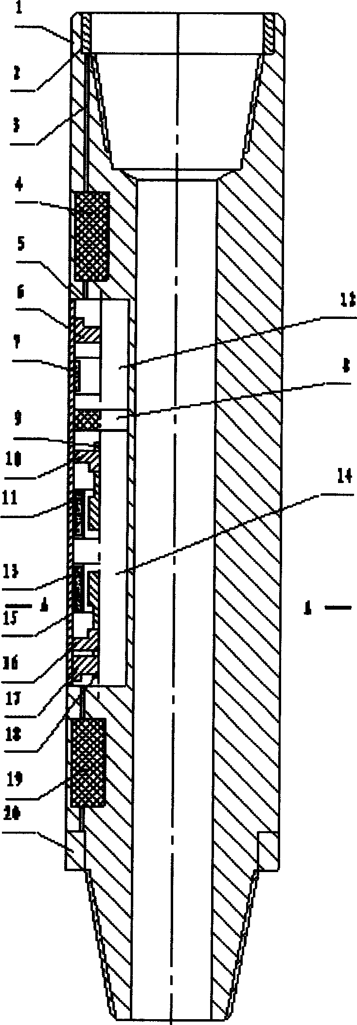
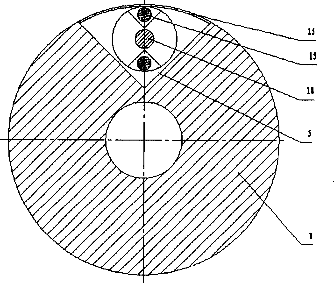
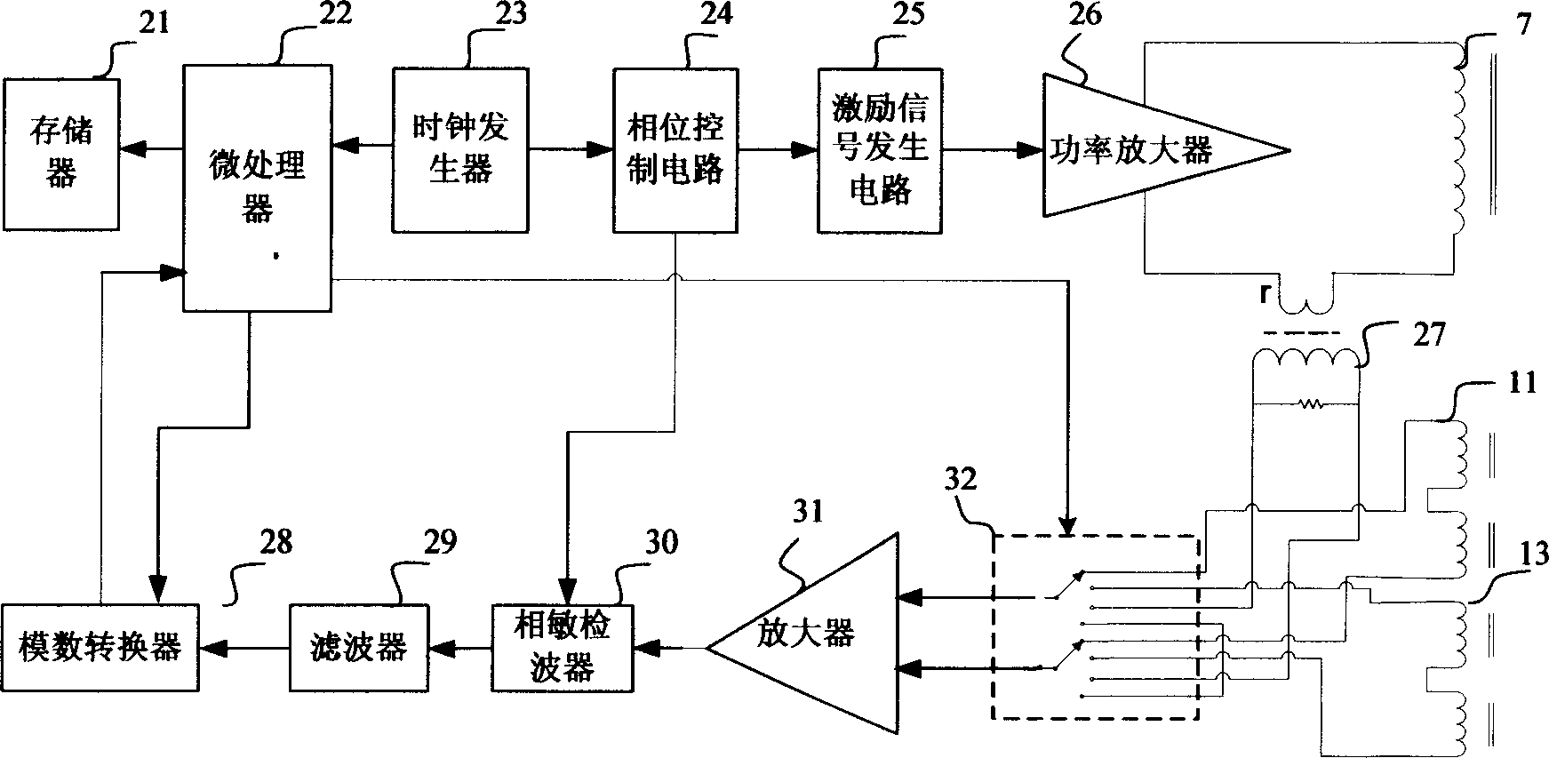
[0030] Now combined with the manual figure 1 , 2 and 3, the present invention is further described.

[0031] figure 1 with figure 2 Represents the axial and radial sections of the instrument. The drill collar 1 is used as the installation skeleton of the instrument and a part of the downhole drilling tool, and is located behind the drill bit or the deflection tool. There is a V-shaped groove 5 on any side of the drill collar. The coupling unit 8 connects the transmitting unit 12 and the receiving unit 14 and installs them in the V-shaped groove 5 to form an electrode system. The high-pressure sealing cover plate 15 is pressed on the V-shaped groove. 5, the transmitting unit 12 is equipped with a transmitting coil 7 and a hydraulic balance piston 6, and the receiving unit 14 is equipped with a deep detection receiving coil 11, a deep detection balance adjustment screw sleeve 10, a deep detection balance adjustment screw 9, and a shallow detection receiver. Coil 13, shallo...


PUM


Abstract

The invention relates to a double induction unit resistance meter that includes drill collar, V shaped groove, emitting unit, coupling unit, receiving unit, emitting circuit module, receive controlling circuit module, high pressure sealing cover board, upper sliding circle connector, down sliding circle connector, and wire hole. It could test two ground unit resistance and the emitting coil and the receiving coil are independent. It could test the ground unit resistance real time in drilling process, and could explain the ground invade situation and calculate ground water saturation, distinguish the lithology of the layer location and the hydro-alteration feature. It is suitable to take ground guides in well drilling projects.

Description

Technical field: [0001] The invention relates to a wireless measuring-while-drilling instrument used for geosteering in petroleum drilling engineering. Background technique: [0002] At present, in the field of measurement while drilling in the drilling industry, the formation resistivity is used to divide the formation profile and determine the oil saturation of the reservoir, which is the main basis for logging interpretation and evaluation of oil and gas reserves. Known resistivity measurement techniques while drilling include lateral resistivity while drilling, electromagnetic wave propagation resistivity and induction resistivity while drilling. [0003] In shallow lateral resistivity logging while drilling, the power supply electrodes supply current to form an electric field in the formation around the wellbore, measure the distribution of the electric field in the formation, and obtain the formation resistivity. The LWD shallow lateral resistivity logging tool uses t...

Claims


Application Information

Patent Timeline
Patent Type & Authority Applications(China)
IPC IPC(8): E21B47/02
Inventor 杨锦舟张海花肖红兵韩建来孙莉莉
Owner 中石化石油工程技术服务有限公司
Learn More