
A system and method of determining a position of a radiation scattering/reflecting element

A technology of reflector and internal reflection, applied in the field of position systems, can solve problems such as easy breakage and easy damage to touch panels

Inactive Publication Date: 2006-11-22
FLATFROG LAB
View PDF3 Cites 16 Cited by
  • Summary
  • Abstract
  • Description
  • Claims
  • Application Information

AI Technical Summary

Problems solved by technology

[0002] There are many different technologies in the finger touch / trackpad space, but most of them suffer from the fact that the actual trackpad is fragile and breaks easily

Method used


Image

  • A system and method of determining a position of a radiation scattering/reflecting element
  • A system and method of determining a position of a radiation scattering/reflecting element
  • A system and method of determining a position of a radiation scattering/reflecting element

Examples


Embodiment Construction

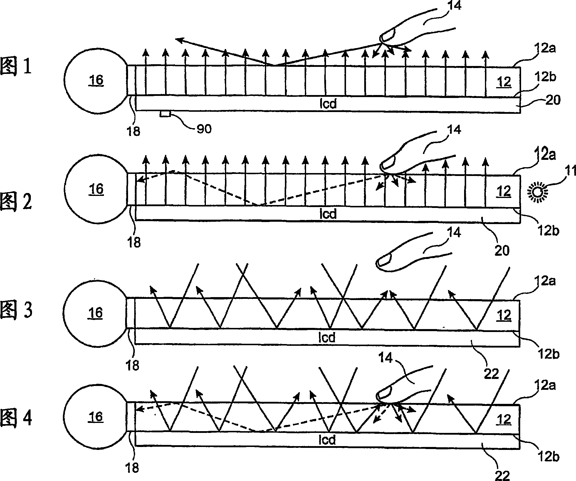
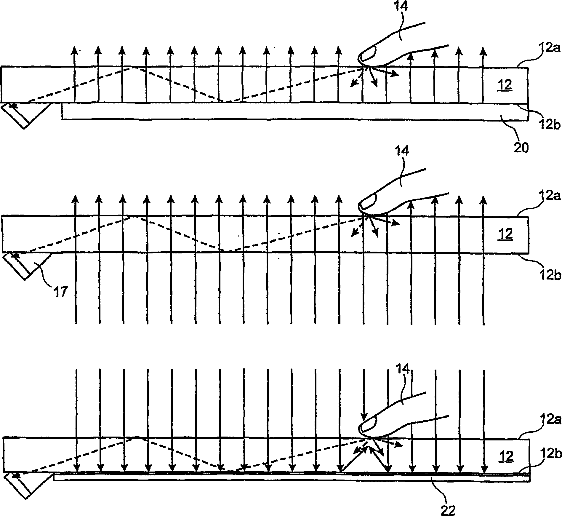
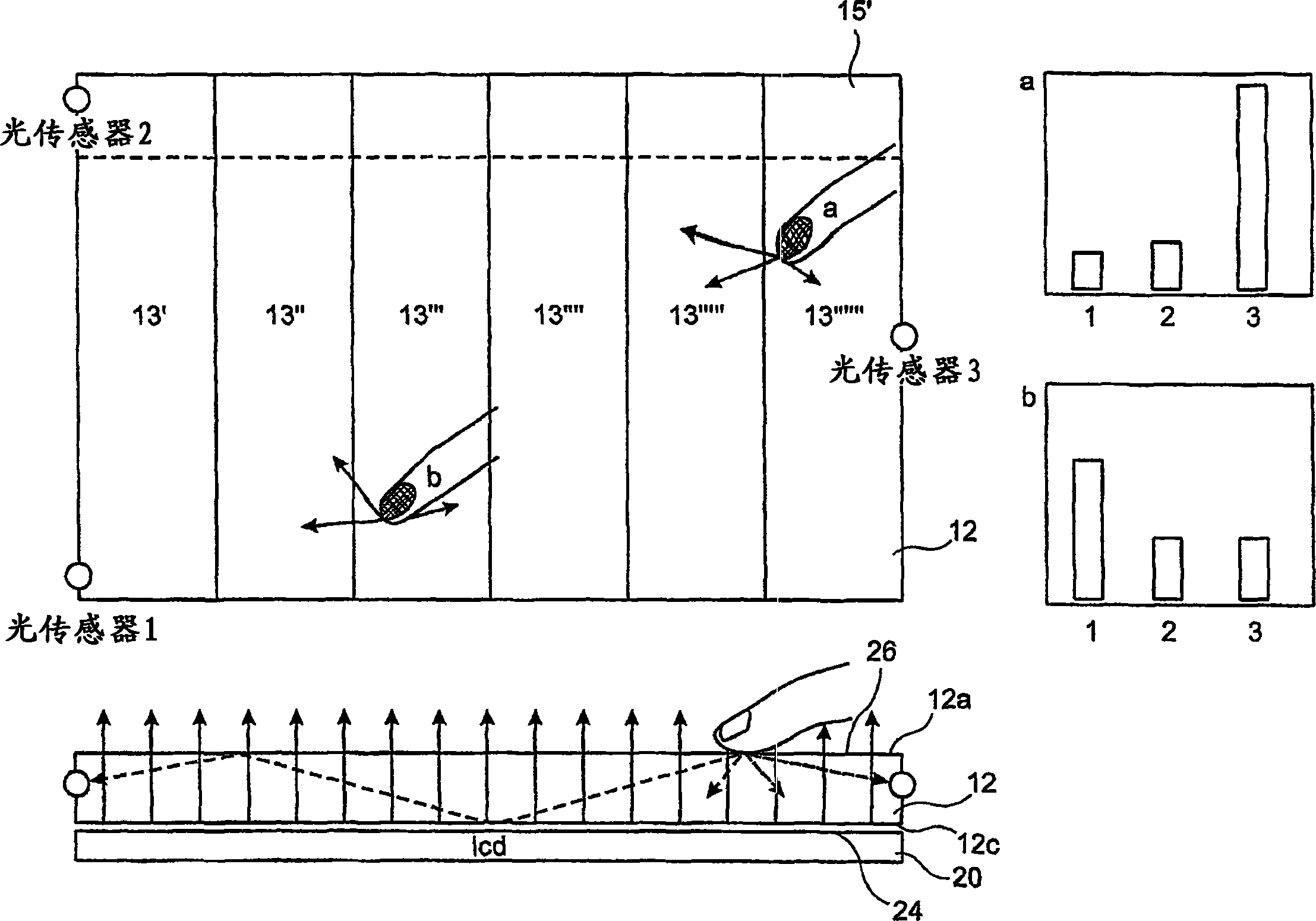
[0110] The full functionality of the invention is shown in Figures 1-4, where a light transmissive member in the form of a plate 12 has a surface 12a adapted to be engaged by a reflective / scattering member in the form of a finger 15 here. Visible light - used in this embodiment but could be substituted by any electromagnetic radiation - passes to the plate 12 and is emitted / scattered by the finger 14 at the surface 12a where the finger 14 touches the surface. At other locations on the surface 12a the light will either leave the plate 12 or be reflected back to the plate 12 towards the opposite surface 12b of the plate 12 .

[0111] The light reflected / scattered by the finger 14 is reflected in multiple directions, and part of the emitted / scattered light will then be directed by the plate 12 .

[0112] The detector 16 is arranged to be able to receive the light directed by the plate 12 . In the present embodiment, the detector 16 is arranged at an edge portion of the plate 12 ...


PUM


Abstract

A method and system for determining the position of a radiation scattering / reflecting element, where the radiation emitter is provided at a surface of a radiation transmissive element an on which radiation is incident. This incident radiation is scattered / diffused / reflected by the scattering / reflecting element and guided by the transmissive element toward a detector able to determine the position of the element.

Description

technical field [0001] The present invention relates to a system and method for determining the position of radiation scattering / reflecting / diffusing elements, and in particular to touchpads or the like for eg finger touch. Background technique [0002] There are many different technologies in the finger touch / trackpad space, but most of them suffer from the fact that the actual trackpad is fragile and breaks easily. [0003] Generally, touchpads are generally described in eg US-A-4346376, 4484179, 4668933, 5945981 and 6122394 and US2003 / 0048257 and 2003 / 0052257. Contents of the invention [0004] The present invention relates to a non-flat, simple and inexpensive touchpad technology that can be used with many different types of objects such as fingers and inactive (only reflect or scatter incident radiation) objects. [0005] In a first aspect, the invention relates to a system for determining the position of a radiation reflecting / scattering element, the system comprisi...

Claims


Application Information

Patent Timeline
Patent Type & Authority Applications(China)
IPC IPC(8): G06F3/033G06F3/041G06F3/042G06K11/00
CPCG06F3/0421G06F2203/04106G06F2203/04109
Inventor 尤纳斯·奥威·菲利普·埃利亚森简斯·瓦根布拉斯特·斯图贝·斯特尔加德
Owner FLATFROG LAB
Learn More