
Integrated PUF

A component and radiation scattering technology, applied in the field of devices forming challenge-response pairs, can solve the problems of expensive, impossible precise positioning, and difficulty in replicating optical PUF, and achieve the effect of easy alignment and easy manufacture

Inactive Publication Date: 2008-10-22
KONINKLIJKE PHILIPS ELECTRONICS NV
View PDF1 Cites 3 Cited by
  • Summary
  • Abstract
  • Description
  • Claims
  • Application Information

AI Technical Summary

Problems solved by technology

Replicating optical PUFs is very difficult since precise positioning of the scattering elements in replicas is practically impossible and very expensive to obtain even if the exact location of the scattering elements is known

Method used


Image

  • Integrated PUF
  • Integrated PUF
  • Integrated PUF

Examples


Embodiment Construction

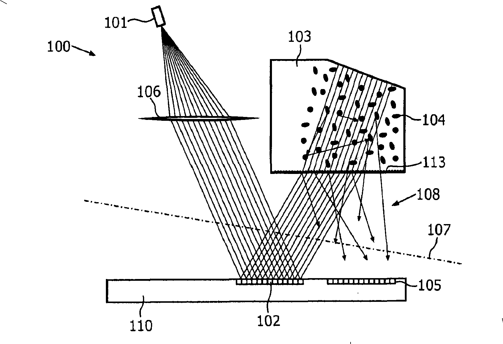
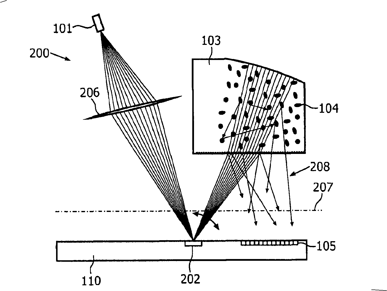
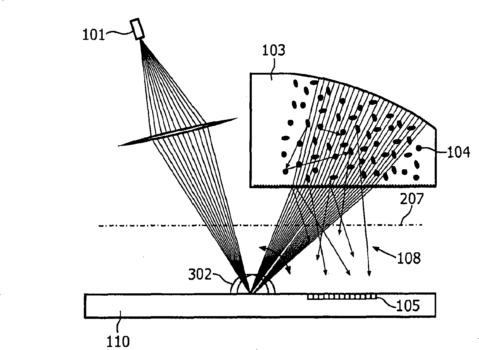
[0032] figure 1 A schematic cross-sectional side view of an apparatus 100 for forming challenge-response pairs according to the invention is shown. The laser diode 101 is arranged to emit light to a light scattering element 103 , which is a light transmissive material containing randomly distributed light scattering particles 104 . Light incident on the scattering element is randomly scattered onto the plurality of photodetectors 105 . Therefore, light scattering elements have challenges in the form of light emitted by laser diodes.

[0033] In addition, the device 100 comprises a challenge modification element 102 for changing the challenge, ie modifying the radiation incident on the radiation scattering element 103 so that different radiation patterns are detected by the radiation detection element 103 . Advantageously, said device 100 comprises an optical element 106 substantially collimating the laser beam so as to distribute said laser light uniformly over the active ar...


PUM


Abstract

In a device for providing challenge-response pairs a radiation detection element, a challenge-modifying element and preferably also a light source are arranged on the same side of an imaginary plane, which separates said radiation-detecting element from a radiation scattering element. Hence, generation of a speckle pattern having a desired minimum speckle size is facilitated and a more easily assembled device is provided.

Description

technical field [0001] The invention relates to a device for forming challenge-response (challenge-response) pairs. Background technique [0002] For example WO2005 / 048179 has disclosed the use of "Physically Unclonable Functions" (PUFs) for security purposes. After integrating PUFs into products such as smart cards, chips or storage media, it is difficult to produce replicas of the products. In this literature, "clone" means a physical copy of a product or a model capable of reliably predicting the input-output behavior of a product. Physical copying is very difficult because PUF manufacturing is an uncontrollable process and PUFs are very complex objects. Due to the complexity of PUFs, accurate modeling is very difficult; slightly changing the input can lead to a greatly skewed output. The uniqueness and complexity of PUFs make them ideal for identification, authentication or key generation purposes. [0003] Typically, the proving party should prove the access secret ...

Claims


Application Information

Patent Timeline
IPC IPC(8): H04L9/32
CPCH04L9/3278G02B26/026G02B26/0833H04L2209/805G02B5/02G02B27/00G06F21/73G09C1/00
Inventor W·G·奥菲B·斯科里克P·T·图伊尔斯
Owner KONINKLIJKE PHILIPS ELECTRONICS NV
Learn More