
Radiation scatter protection system

a radiation scattering and protection system technology, applied in the field of radiation scattering protection systems, can solve the problems of significant injury to the wearer, potential to produce a significant radiation hazard over the working lifetime of the worker, and hazard to the worker

Active Publication Date: 2019-11-21
BAIRD DAVID A +2
View PDF0 Cites 4 Cited by
  • Summary
  • Abstract
  • Description
  • Claims
  • Application Information

AI Technical Summary

Benefits of technology

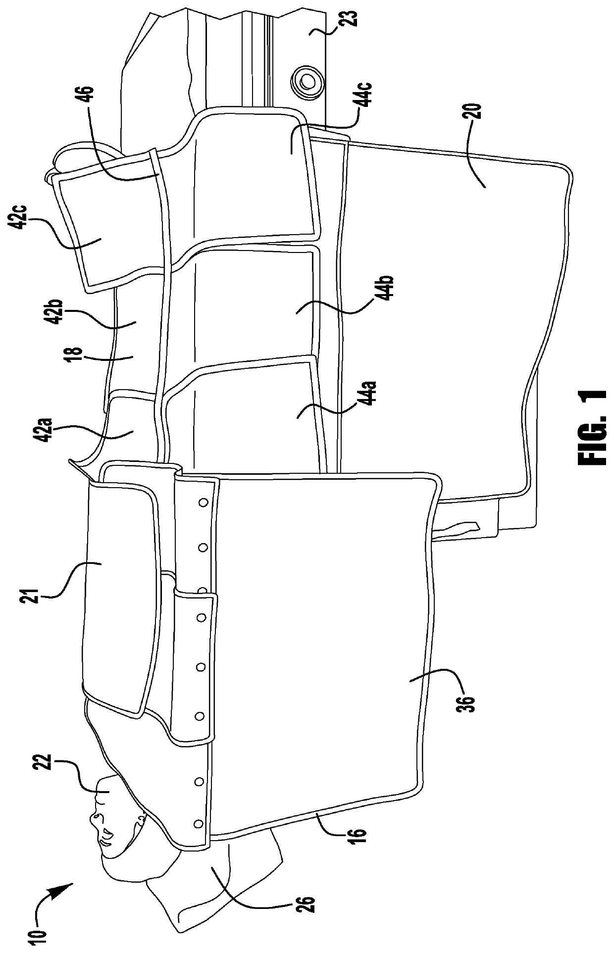
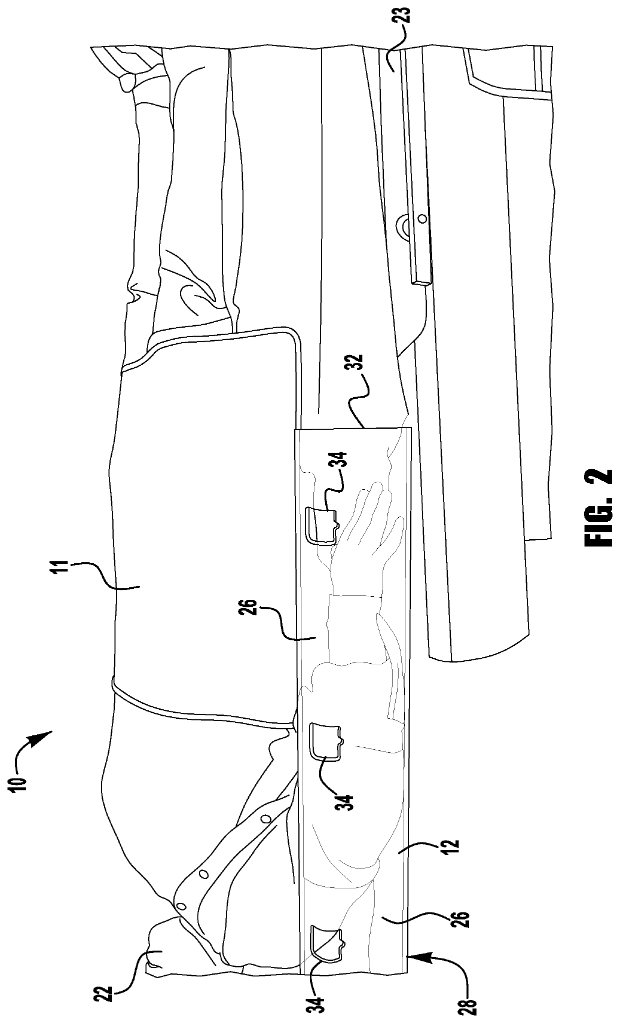
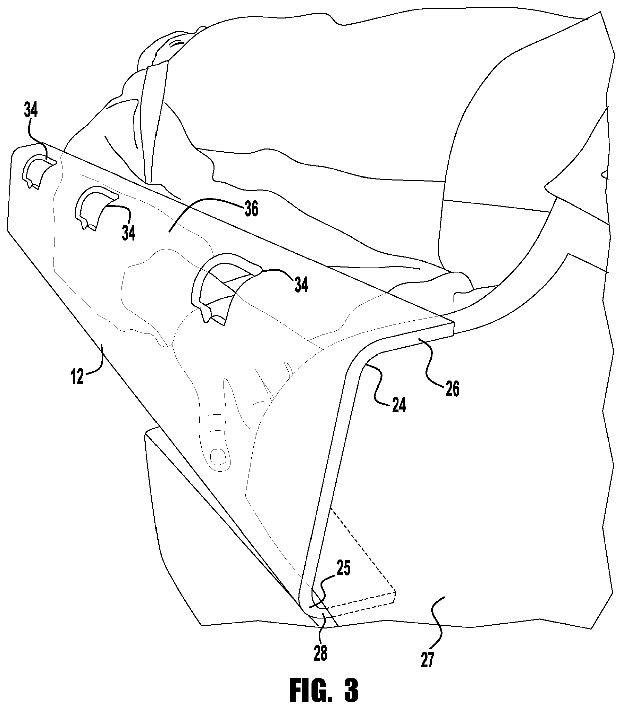
The present invention provides a radiation scatter protection system that can be attached to an X-ray table to protect both medical staff and patients from excessive exposure to radiation. The system includes an arm board, arm board shielding, a sand bag shield, a side curtain shield, and a throw shield, which all work together to minimize the risk of radiation-related health hazards. The method for attaching the system involves placing the arm board around the patient's arm, adding the shielding to the arm board, placing a sand bag shield on top of the patient, hanging a side curtain shield from the X-ray table, and adding a throw shield on top of the patient.

Problems solved by technology

The hazard to the worker arises from x-rays scattered by the patient's body toward the worker.
Exposure to this scattered radiation has the potential to produce a significant radiation hazard over the working lifetime of the worker.
Unfortunately, lead garments are heavy and can cause significant injury to the wearer with daily use over a working lifetime.
It is now realized, however, that the danger to the worker is primarily caused by radiation reflected from the patient's body, so-called “scattered radiation”.
An additional problem, however, arises from the fact that many of these lower atomic number heavy metals reradiate the x-rays they absorb, albeit at lower energy levels.
This can lead to a problem where the exposure to the wearer is greater than that evident from the attenuation tests.

Method used


Image

  • Radiation scatter protection system
  • Radiation scatter protection system
  • Radiation scatter protection system

Examples


Embodiment Construction

[0019]In the description that follows, numerous details are set forth in order to provide a thorough understanding of the present invention. It will be appreciated by those skilled in the art that variations of these specific details are possible while still achieving the results of the present invention. Well-known processing steps are generally not described in detail in order to avoid unnecessarily obfuscating the description of the present invention.

[0020]In the description that follows, exemplary dimensions may be presented for an illustrative embodiment of the invention. The dimensions should not be interpreted as limiting. They are included to provide a sense of proportion. Generally speaking, it is the relationship between various elements, where they are located, their contrasting compositions, and sometimes their relative sizes that is of significance.

[0021]In the drawings accompanying the description that follows, often both reference numerals and legends (labels, text de...


PUM


Abstract

A radiation scatter protection system designed to attach to an X-ray table to limit exposure to radiation for both medical staff and patient. The radiation scatter protection system includes an arm board adapted to be disposed around an arm of the patient; an arm board shielding including one large sheet of shielding extending downward from the X-ray table and a plurality of additional sheets of shielding, removably mounted to the arm board; a sand bag shield including a plurality of sheets of top shielding and a plurality of sheets of bottom shielding which connect to an elongated, cylindrical sandbag; a side curtain shield hanging from the X-ray table; and a throw shield.

Description

CROSS REFERENCE TO RELATED APPLICATIONS[0001]This application claims the benefit of U.S. Provisional Patent Application No. 62 / 672,688 filed on May 17, 2018, which is incorporated in its entirety by reference herein.TECHNICAL FIELD OF THE INVENTION[0002]The present invention relates to a radiation scatter protection system, and more particularly to protection system designed to limit exposure to radiation for both medical staff and patients.BACKGROUND OF THE INVENTION[0003]In the medical field, personnel are often required to work in close proximity to patients undergoing imaging procedures involving x-rays, commonly referred to as fluoroscopy. The hazard to the worker arises from x-rays scattered by the patient's body toward the worker. Although such scattered radiation has a lower energy level than the direct x-ray beam, it does maintain its ionizing potential. Exposure to this scattered radiation has the potential to produce a significant radiation hazard over the working lifetim...

Claims


Application Information

Patent Timeline
IPC IPC(8): A61B6/10G21F3/00G21F1/12A61B6/04
CPCA61B6/107A61B6/0407G21F3/00G21F1/125A61B6/487G21F1/106
Inventor BAIRD, DAVID A.HINK, THOMAS P.LEONE, DENIO A.
Owner BAIRD DAVID A
Learn More