
Piezoelectric incapacitation projectile

A technology of incapacity and piezoelectric elements, applied in the direction of warheads, ammunition, projectiles, etc., can solve the problem of rapid subduing targets and complex problems

Inactive Publication Date: 2006-11-22
MDM GRP
View PDF1 Cites 3 Cited by
  • Summary
  • Abstract
  • Description
  • Claims
  • Application Information

AI Technical Summary

Problems solved by technology

Aside from the firing operation, the series of affairs of the equipment unnecessarily complicates the rapid subjugation of targets
Maneuvers that require first-time uniforms to fire projectiles cause human error to perform a series of transactions fraught with tension, which will prove to be critical

Method used


Image

  • Piezoelectric incapacitation projectile
  • Piezoelectric incapacitation projectile
  • Piezoelectric incapacitation projectile

Examples


Embodiment Construction

[0024] The following description is an example of the best mode of the invention, including using the invention as a firearm projectile. This description is not meant to limit or define the scope of the invention, but illustrates the general principles of the invention. While certain novel features of the invention have been shown and described, and referred to in the appended claims, it will be understood that those skilled in the art may vary the form and details of the apparatus shown without departing from the spirit of the invention. Various omissions, substitutions and changes are made to its operation.

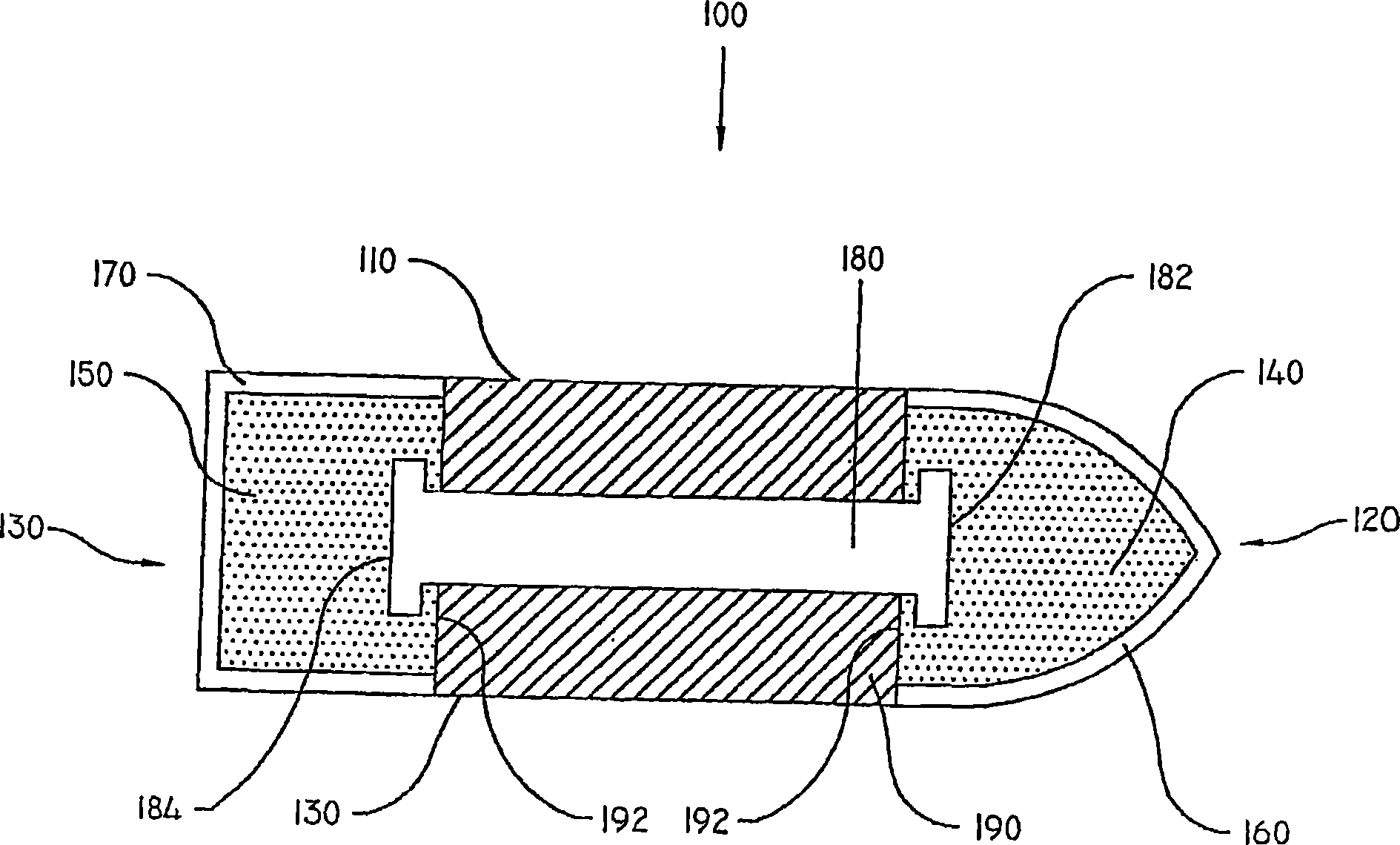
[0025] refer to figure 1 , the projectile 100 includes a body 110 disposed between a nose end 120 and a base end 130 . The front end 120 houses a front electrode 160, which is constructed of a tip-cusp conductive material such as copper. Alternatively, any conductive material can be used. The front electrode 160 is used for initial contact with a target (not shown),...


PUM


Abstract

An incapacitating piezoelectric projectile comprises a projectile body housing a piezoelectric element, at least one electrically conductive contact surface, and a means for coupling said piezoelectric element to said at least one electrically conductive contact surface. Projectile is arranged so that an impact will cause the piezoelectric element to discharge an electrical shock to the target through the at least one electrically conductive contact surface, thereby incapacitating the target. The projectile is particularly suitable for use in a method of instantly incapacitating human and non human targets.

Description

technical field [0001] The present invention relates to striking devices, in particular to disabling piezoelectric projectiles that release a voltage upon impact and related methods of use. Background technique [0002] Law enforcement officers often encounter adversaries in the wild. The usual method of engagement is through the use or threat of use of deadly weapons, including the use of firearms and standard shooting techniques. However, conventional firearms have limitations for instantly incapacitating or stopping an adversary. Barring a direct hit to the head or spinal cord, the adversary remains combative until blood loss or heart failure leaves him starved of oxygen and unconscious. To compensate for blows that cannot be incapacitated by a single shot, most combat shooting systems teach a method of targeting the "center of gravity," which relies on multiple strikes to stop the opponent. This often results in incurable trauma and death to the adversary. In one wel...

Claims


Application Information

Patent Timeline
IPC IPC(8): F42B30/02F42B12/36
CPCF41H13/0031F42B12/36
Inventor 约翰·勒布儒瓦
Owner MDM GRP
Learn More