
Plasma display panel

A plasma and display panel technology, applied in alternating current plasma display panels, gas discharge electrodes, gas discharge tubes/containers, etc., can solve the difficulty in achieving white balance, the plasma display panel is not considered, and the manufacturing cost of the plasma display panel Increase and other problems to achieve the effect of improving brightness, achieving white balance, and improving luminous efficiency

Inactive Publication Date: 2006-11-15
LG ELECTRONICS INC
View PDF0 Cites 2 Cited by
  • Summary
  • Abstract
  • Description
  • Claims
  • Application Information

AI Technical Summary

Problems solved by technology

[0020] As mentioned, for the discharge of the plasma display panel, in general, it is difficult to achieve white balance because the discharge is generated non-uniformly
[0021] In addition, although the ITO electrode area where the discharge is generated is fixed, it is not considered in conventional plasma display panels.
As a result, there is a problem that the manufacturing cost of the plasma display panel increases because expensive ITO is used for the ITO electrode area where no discharge is generated

Method used

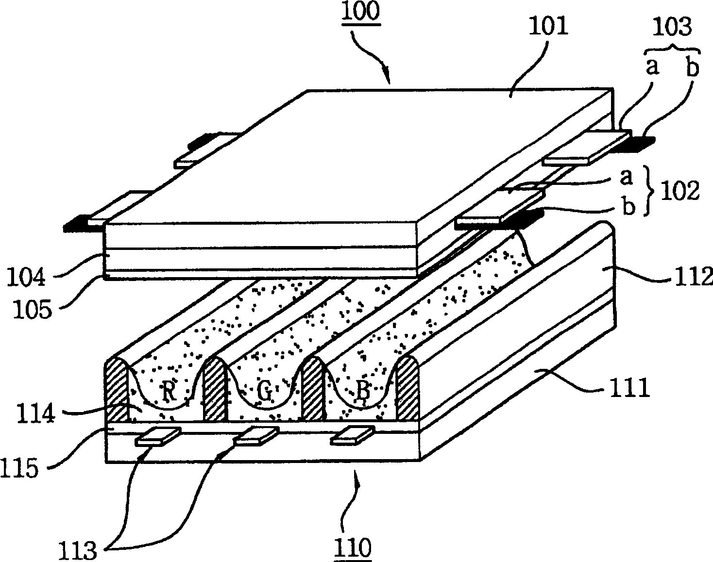
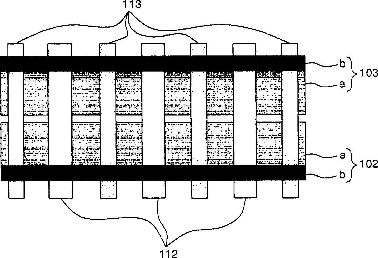
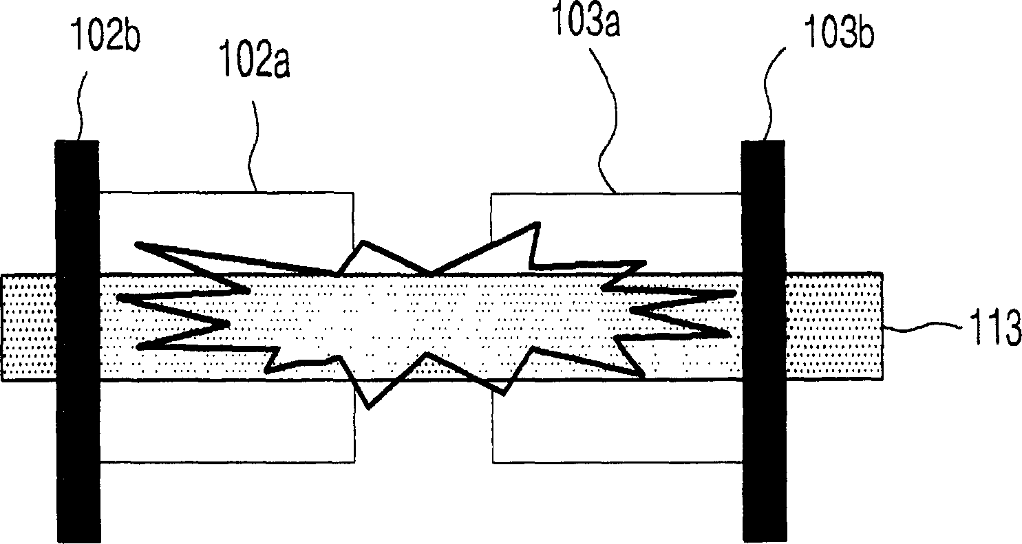

Image

  • Plasma display panel
  • Plasma display panel
  • Plasma display panel

Examples


Embodiment Construction

[0039] Reference will now be made in detail to the embodiments of the present invention, examples of which are illustrated in the accompanying drawings.

[0040] A plasma display panel according to an aspect of the present invention includes: a front substrate including scan electrodes and sustain electrodes; and a rear substrate including barrier ribs for forming discharge cells, wherein the scan electrodes and sustain electrodes include a plurality of protruding electrodes in the discharge cells section.

[0041] The protruding electrode part may include a first protruding electrode part and a second protruding electrode part.

[0042] The first protruding electrode part may be disposed between the second protruding electrode part.

[0043] The first protruding electrode part may include at least one protruding electrode.

[0044] The second protruding electrode part may include at least two protruding electrodes.

[0045] The first gap between the first protruding electrode por...


PUM


Abstract

The present invention relates to a plasma display panel, particularly, to a plasma display panel equipped with an electrode structure which can perform readily a discharge between a scan electrode and a sustain electrode. A plasma display panel according to an aspect of the present invention comprises a front substrate comprising a scan electrode and a sustain electrode; and a rear substrate comprising a barrier rib for forming a discharge cell, wherein the scan electrode and the sustain electrode comprise a plurality of projecting electrode parts in the discharge cell. The present invention modifies the shape of the transparent electrode to broaden the discharge area, so that the luminous efficiency increases to improve a luminance. Moreover, since a stable and uniform discharge is generated, the white balance can be efficiently implemented. In addtion, the unnecessary expensive ITO area is removed and the fabrication cost of the plasma display panel can be lowered.

Description

Technical field [0001] The present invention relates to a plasma display panel, and more particularly to a plasma display panel equipped with an electrode structure that can easily perform discharge between scan electrodes and sustain electrodes. Background technique [0002] In general, the plasma display panel includes barrier ribs formed between the front panel and the rear panel. The barrier and the front and rear panels together form a unit. Each cell is filled with a main discharge gas, such as neon Ne, helium He, or a mixed gas including Ne and He. In addition, each cell contains an inert gas including a small amount of xenon. If a high-frequency voltage is used to discharge the inert gas, ultraviolet rays are generated. Ultraviolet rays excite the light-emitting phosphor in each cell, thus producing a visible image. [0003] figure 1 It is a perspective view showing the structure of a conventional plasma display panel. [0004] Such as figure 1 As shown, for this plasm...

Claims


Application Information

Patent Timeline
Patent Type & Authority Applications(China)
IPC IPC(8): H01J11/12H01J11/22H01J11/24H01J11/26H01J11/32H01J11/34H01J11/36H01J11/38H01J11/40H01J11/42H01J11/50
CPCH01J11/12H01J11/24H01J11/32H01J2211/245H01J2211/323
Inventor 徐泳佑
Owner LG ELECTRONICS INC
Learn More