Gas insulating switch device

A gas-insulated switch, contact position technology, used in switchgear, switchgear settings, electrical switches, etc.

Active Publication Date: 2006-11-15
LSIS CO LTD
View PDF0 Cites 14 Cited by
  • Summary
  • Abstract
  • Description
  • Claims
  • Application Information

AI Technical Summary

Problems solved by technology

Thus, resulting in undesired intermittent operation (ie, intermittent operation)

Method used


Image

  • Gas insulating switch device
  • Gas insulating switch device
  • Gas insulating switch device

Examples


Embodiment Construction

[0027] Reference will now be made in detail to the preferred embodiments of the invention, examples of which are illustrated in the accompanying drawings.

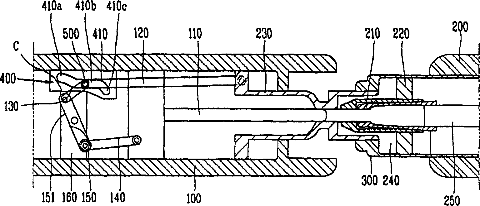
[0028] image 3 is a side sectional view showing a gas insulated switchgear in a closed state (ON state) according to the present invention.

[0029] like image 3 As shown, the gas insulated switchgear according to the present invention includes a first stationary contact 100 and a second stationary contact 200 facing each other at a predetermined distance and electrically connected to a power supply terminal and a load terminal, respectively.

[0030] The movable contact 300 is linearly movably mounted on the second stationary contact 200 to move to a contact position contacting the first stationary contact 100 or to a separation position away from the first stationary contact 100 .

[0031] The piston rod 250 is connected to the movable contact 300 using a driving connection unit such as a driving connection pin (not ...


PUM


Abstract

The invention discloses a gas insulated switchgear capable of stably and continuously transmitting driving force between two arc contacts with a certain time delay in a bidirectional driving method. The gas insulated switchgear includes: a plurality of links for driving force transmission; and a slot guide member having a rotation guide portion and a linear motion guide portion for a connecting shaft between the two links.

Description

technical field [0001] The present invention relates to a gas insulated switchgear, and more particularly, the present invention relates to a gas insulated switchgear which can achieve driving force transmission smoothly, continuously and with a delay by improving the driving force transmission structure in a bidirectional driving method. In this bidirectional driving method, when a driving force is transmitted from one of the two arcing contacts to the other, the two arcing contacts move in different directions, thereby causing them to contact or separate from each other. Background technique [0002] The function of gas insulated switchgear or gas insulated circuit breaker is to protect the power system and electrical equipment by automatically disconnecting the electrical circuit when the circuit is opened / closed under normal conditions or when a large current is generated due to ground fault or electrical short circuit. Gas insulated switchgear is installed in extra-high...

Claims


Application Information

Patent Timeline
Patent Type & Authority Applications(China)
IPC IPC(8): H01H33/42H01H33/22
CPCH01H33/42H01H2033/028H01H33/021H01H33/70H01H33/91H01H71/123H02B13/035
Inventor 吕振旭李基祯崔钟雄姜圣模
Owner LSIS CO LTD
Why Eureka
Try Eureka