
A circuit breaker action mechanism

A technology of action mechanism and circuit breaker, which is applied in the direction of protection switch operation/release mechanism, etc., can solve the problems of low reliability and complex structure of circuit breaker action mechanism, and achieve the effect of simple structure

Active Publication Date: 2017-11-24
JAECELE ELECTRIC
View PDF1 Cites 0 Cited by
  • Summary
  • Abstract
  • Description
  • Claims
  • Application Information

AI Technical Summary

Problems solved by technology

[0005] The present invention aims to solve the technical problems of complex structure and low reliability in the circuit breaker operating mechanism of the prior art, and thus provides a circuit breaker operating mechanism with a simple structure and more reliability

Method used


Image

  • A circuit breaker action mechanism
  • A circuit breaker action mechanism
  • A circuit breaker action mechanism

Examples


Embodiment

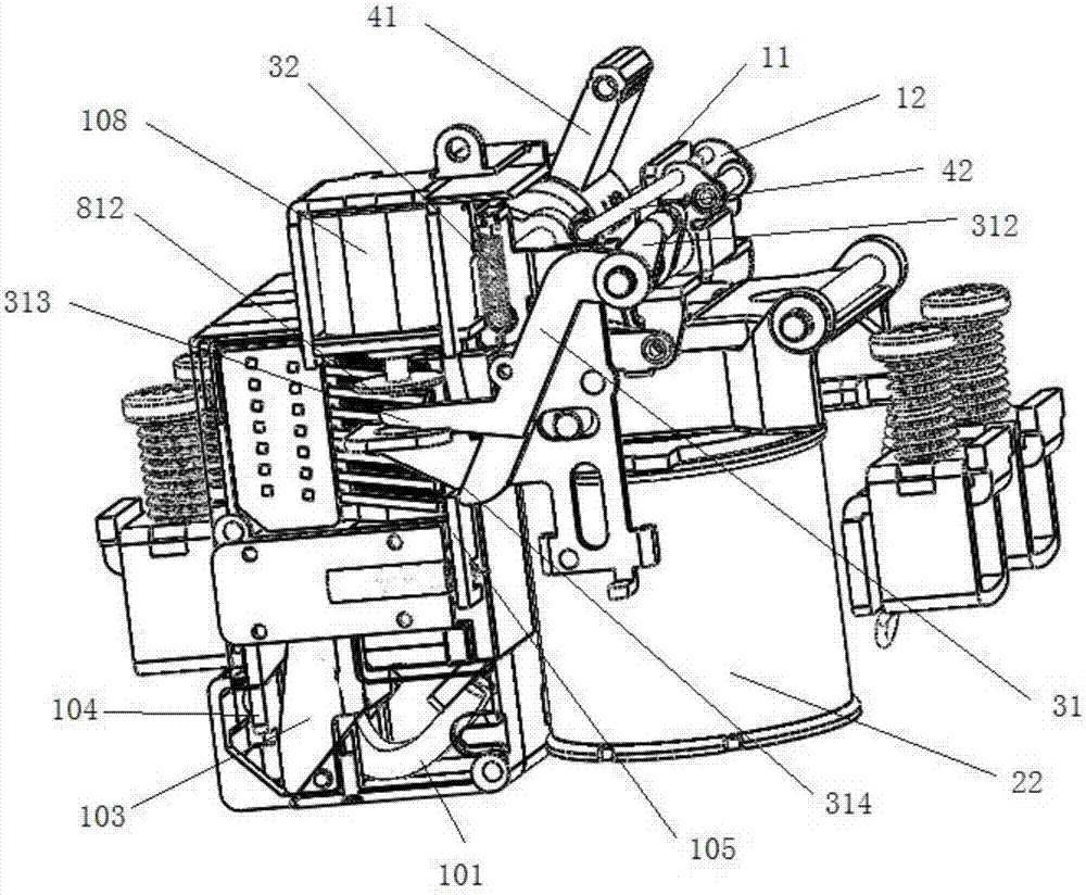
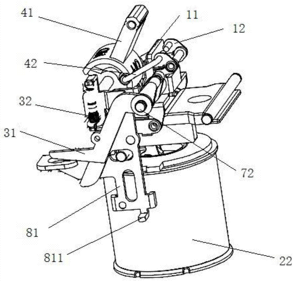
[0074] As provided by the present invention, such as figure 1 , Figure 5 , Figure 7 shown, including:

[0075] An electromagnetic mechanism, including a moving iron core 21, a coil 22, and a static iron core 23;

[0076] The handle 41 can be rotated between the opening position and the closing position corresponding to the opening and closing of the circuit breaker under the action of external force;

[0077] The second connecting rod 42 connects the handle 41 and the release device. When the handle 41 is rotated to the closing position, the rotation angle of the handle 41 is greater than the pivot shafts at both ends of the second connecting rod 42 and the handle 41 The required rotation angle when the center lines of the rotating shaft 73 are coplanar;

[0078] The first drive rod 43 is connected to the handle 41 and the moving iron core 21, and when the handle 41 moves between the closing position and the opening position, it drives the moving iron core 21 to approach...


PUM


Abstract

The invention discloses an actuating mechanism of a circuit breaker. When a handle is rotated to a switch-on position, the rotational angle of the handle is larger than a rotational angle required when pivot shafts at the two ends of a second connection rod are coplanar to a central line of a rotation shaft of the handle, a force to make the handle deviated from a switch-off position is continuously applied to the handle by the second connection rod when the handle is at the switch-on position, so that a force to make the handle returned back to the switch-on position is applied to the handle by a first driving rod can be resisted, self-locking is achieved, a movable iron core can be prevented from keeping away from a static iron core due to power off of a coil, and the movable iron core is maintained in contact with the static iron core; and when a circuit in the circuit breaker encounters an abnormal situation, a tripper is driven by a tripping driving device so that the handle is relieved from self-locking and returns back to the switch-off position from the switch-on position, and a switch-off protection circuit of the circuit breaker is achieved. In the actuating mechanism of the circuit breaker, the second connection rod is arranged to connect the handle and the tripper, the switch-on position is arranged to achieve self-locking, thus, the parts of the original circuit breaker are fully utilized, and the whole actuating mechanism of the circuit breaker is simpler and more reliable in structure.

Description

technical field [0001] The invention discloses an action mechanism of a circuit breaker, which belongs to the field of low-voltage electrical appliances. Background technique [0002] The integrated multifunctional terminal appliance is called control and protection switching appliance (CPS for short) in the world. It is an appliance that integrates the main functions of separate electrical components such as circuit breakers, isolators, and thermal relays. In the application of its circuit breaker, compared with the motor operating mechanism, the electromagnetic mechanism has faster breaking speed and breaking capacity, but when the electromagnetic mechanism is closed, the coil must be energized for a long time to keep the dynamic and static iron core closed, which consumes a lot of energy. A lot of power. Therefore, the electromagnetic mechanism of the circuit breaker can introduce an operating mechanism through which the dynamic and static iron cores can be kept closed e...

Claims


Application Information

Patent Timeline
Patent Type & Authority Patents(China)
IPC IPC(8): H01H71/10H01H71/24
CPCH01H71/10H01H71/24
Inventor 彭全昌刘永华
Owner JAECELE ELECTRIC
Learn More