
Optical detecting device and apparatus for image forming

An optical detection and image technology, applied in optics, electrical recording technology using charge graphics, equipment using electrical recording technology using charge graphics, etc., can solve problems such as adverse effects of optical characteristics, enlarged external dimensions, and mutual interference

Inactive Publication Date: 2006-11-15
RICOH KK
View PDF5 Cites 10 Cited by
  • Summary
  • Abstract
  • Description
  • Claims
  • Application Information

AI Technical Summary

Problems solved by technology

However, in consideration of image density control, etc., it is desirable to perform detection as close as possible upstream from the developing device, so instead of pulling back the detection position of the photosensor, it is better to make the photosensor on the side of the paper conveyance path box surface thinning
[0013] As described above, there is a problem that the external dimensions of the optical detection device that arranges a plurality of photosensors on the same printed circuit board become large.
In addition, if there is an obstacle such as a circuit component on the optical path of the photosensor, there will be a problem that it will adversely affect the optical characteristics.
Furthermore, if the wiring of the sensor circuit is covered with printed circuit boards, there will also be problems of mutual interference

Method used


Image

  • Optical detecting device and apparatus for image forming
  • Optical detecting device and apparatus for image forming
  • Optical detecting device and apparatus for image forming

Examples


Embodiment

[0067] Hereinafter, the present invention will be described by taking as an example an optical detection device having one or more photosensors composed of a printed circuit board, a light-emitting element, a light-receiving element mounted on the printed circuit board, a lens, and a light-shielding member.

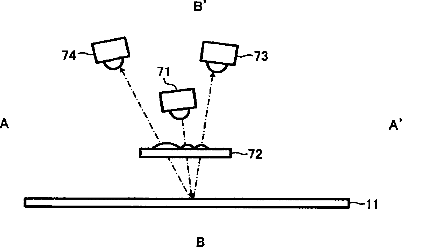
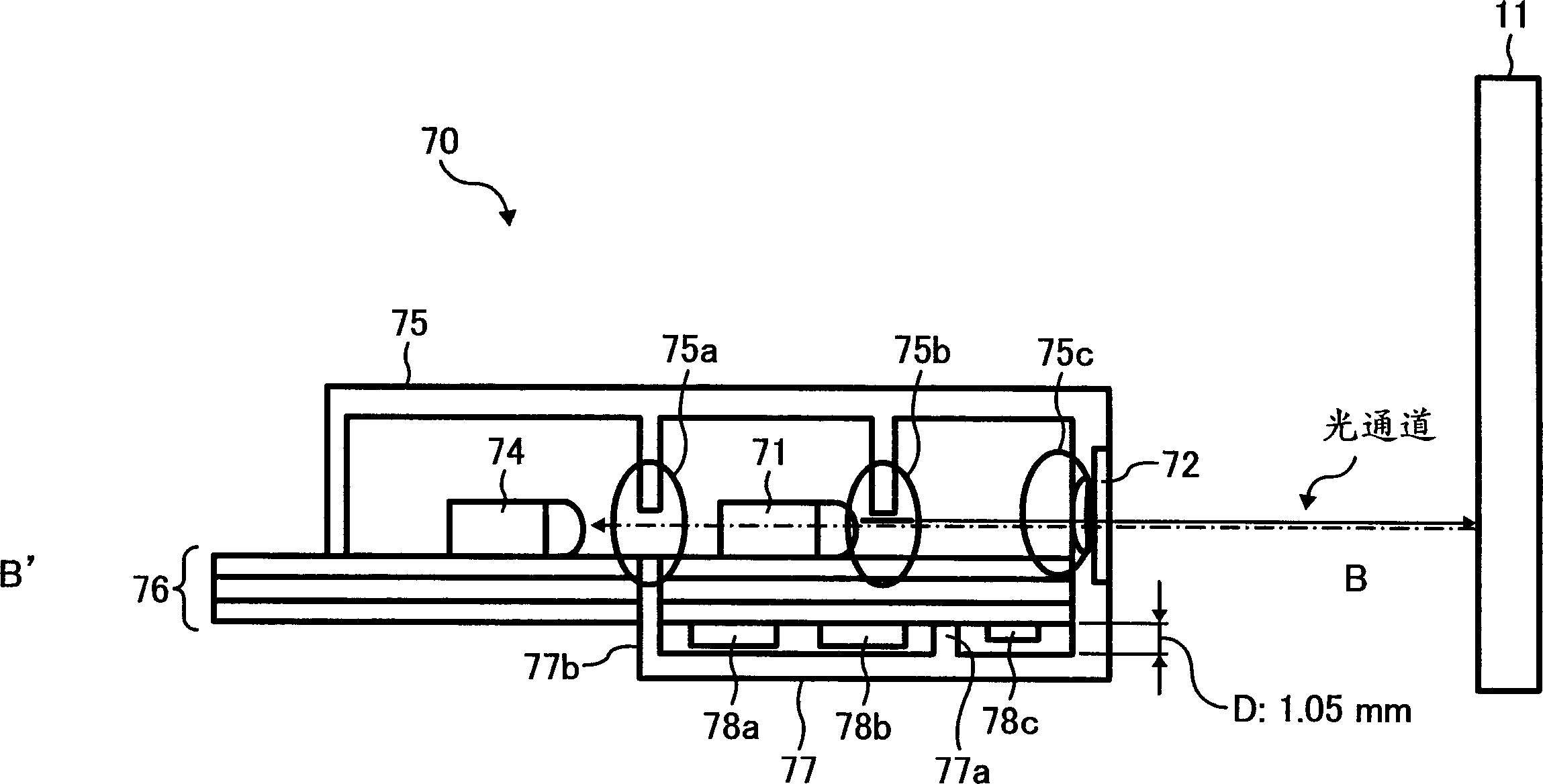
[0068] The existing optical detection device is to install a small number of photosensors 70 on a printed circuit board (for example, in Figure 7 3 in the installation), so it is enough to install the parts only on the surface. but if Figure 4 In this way, when seven photosensors 70 (four for detection of density (amount of toner attached) and three for detection of positional deviation) are mounted on one printed circuit board 76, only the outer surface of the printed circuit board It is impossible to install all the components on the surface. Therefore, in this example, if image 3 as well as Figure 4 As shown, circuit components 78a, 78b, and 78c are arranged an...


PUM


Abstract

Provided is an optical detection device capable of suppressing increase in size, capable of being arranged at a suitable place in an image forming device with many space constraints, and capable of eliminating adverse effects on optical characteristics. In the optical detection device of the "toner image pattern" formed on the detection object, there is at least a printed circuit board 76, a light emitting element 71 and a light receiving element 74 mounted on the printed circuit board, and light shielding members 75 and 77. sensor. In order to detect the surface of the aforementioned detection object, at least one optical sensor will be disposed on the above-mentioned printed circuit board 76, and a part of the optical sensor circuit components 78a, 78b and 78c on the printed circuit board is housed in the aforementioned light shielding member 75 and 77 in.

Description

technical field [0001] The present invention relates to an optical detection device for detecting a "toner image pattern" formed on a detection object such as an image carrier, an intermediate transfer body, or a transfer material conveyance body of an image forming apparatus, and a copying machine provided with the optical detection device , printers, plotters, facsimile machines and other image forming devices. Background technique [0002] JP-A-8-82599 and JP-A-9-89769 disclose techniques for obtaining stable image density in image forming apparatuses such as copiers, printers, plotters, and facsimiles. That is, on the surface of the image carrier (photoreceptor) and the intermediate transfer body, a "toner image sample" for density detection is made, and the density of the "toner image sample" is detected by an optical detection device with a photosensor. to test. Therefore, in such an image forming apparatus, the intensity of writing light for forming a latent image, ...

Claims


Application Information

Patent Timeline
Patent Type & Authority Applications(China)
IPC IPC(8): G03G15/16G03G15/00
CPCG03G15/1605G03G15/235G03G15/6564G03G15/6567G03G2215/0158G03G2215/1623
Inventor 田中加余子藤森仰太长谷川真加藤真治竹内信贵渡边直人平山裕士石桥均有泉修榎并崇史小林一三小林信二内田福年森本亮太
Owner RICOH KK
Learn More