An industrial robot

A technology for robots and handling objects, which is applied in the manufacture of manipulators, conveyor objects, and semiconductor/solid-state devices, etc. It can solve the problems of complicated detection circuits, insufficient rigidity of hand forks, and decreased resonance frequency, and achieve lightweight and improved rigidity. , the effect of increasing the resonance frequency

Inactive Publication Date: 2006-11-15
NIDEC SANKYO CORP
View PDF5 Cites 1 Cited by
  • Summary
  • Abstract
  • Description
  • Claims
  • Application Information

AI Technical Summary

Problems solved by technology

Therefore, a large-capacity suction pump must be used, resulting in an increase in the size and cost of the device 100
In addition, the speed of the detection circuit needs to be increased, so the detection circuit is complicated
[0019] However, the above-mentioned hand fork has a square cross section with the same thickness from the base end to the front end. Therefore, sometimes as the size of the workpiece increases, the hand fork becomes longer and the rigidity is insufficient, or the rigidity is sufficient but it is too heavy.
In either case, the resonance frequency is lowered, making it difficult to speed up the entry and exit of the workpiece.

Method used


Image

  • An industrial robot
  • An industrial robot
  • An industrial robot

Examples


Embodiment Construction

[0048] The composition of the present invention will be described in detail below with reference to the preferred embodiments shown in the accompanying drawings.

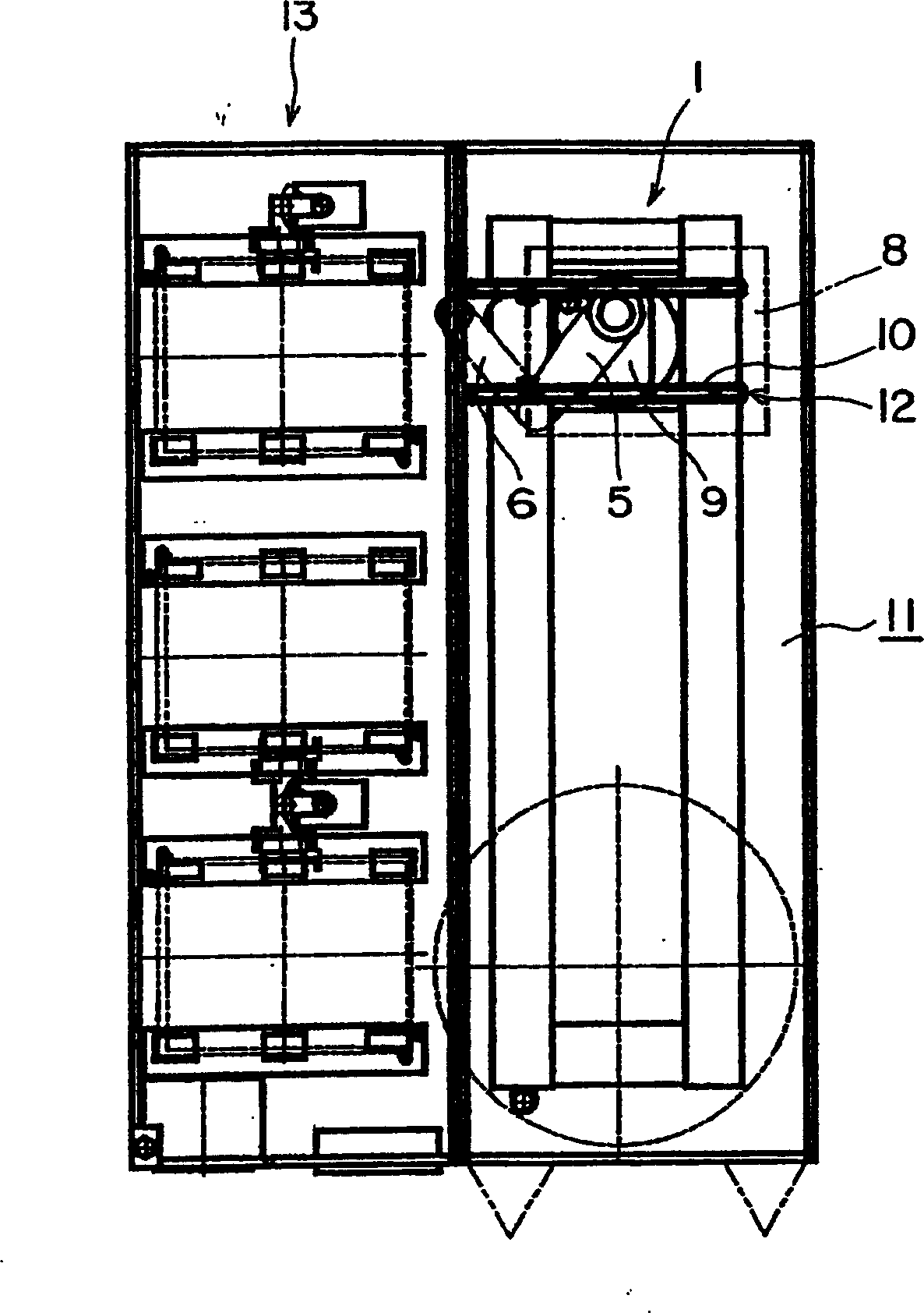
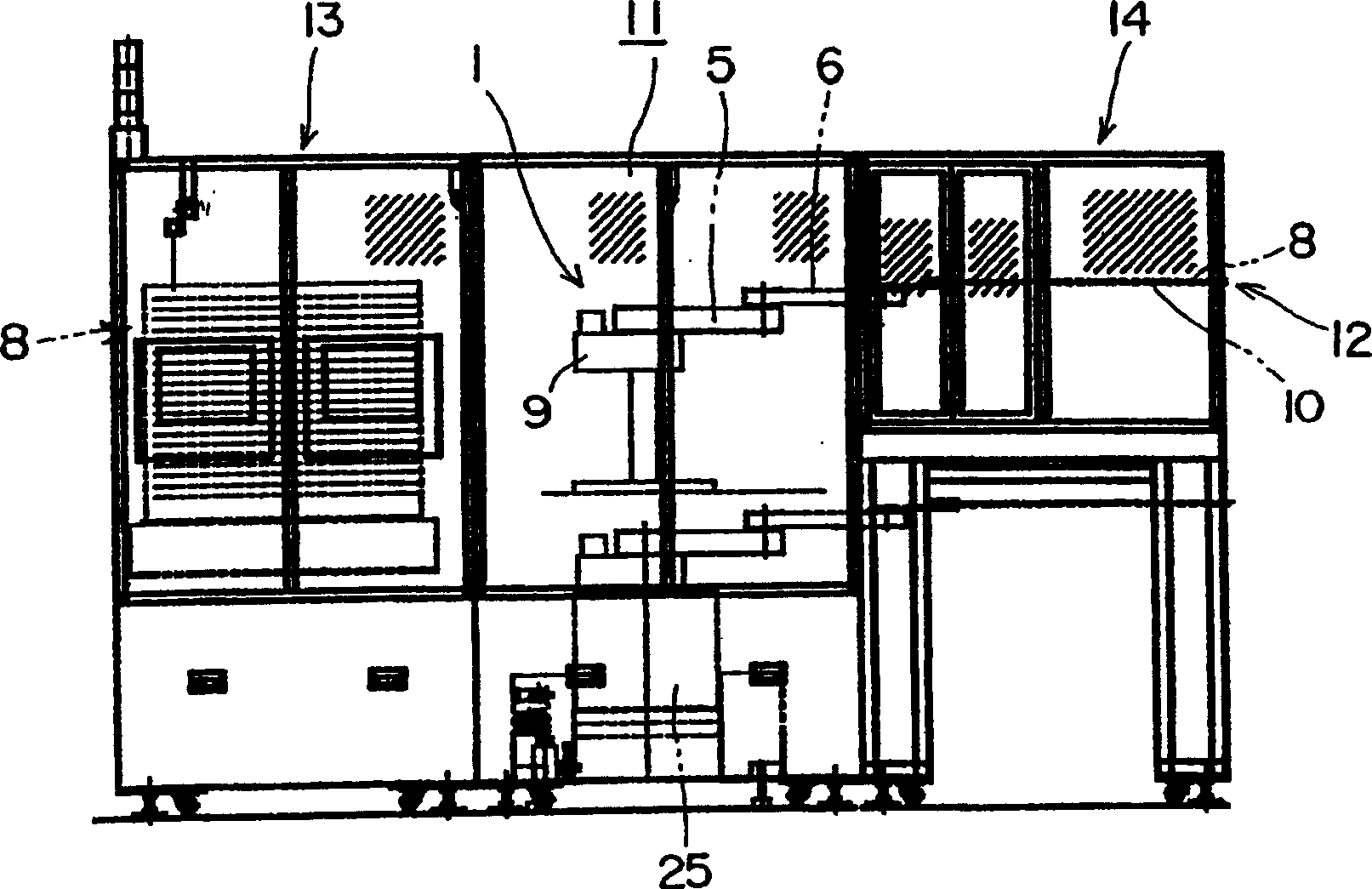
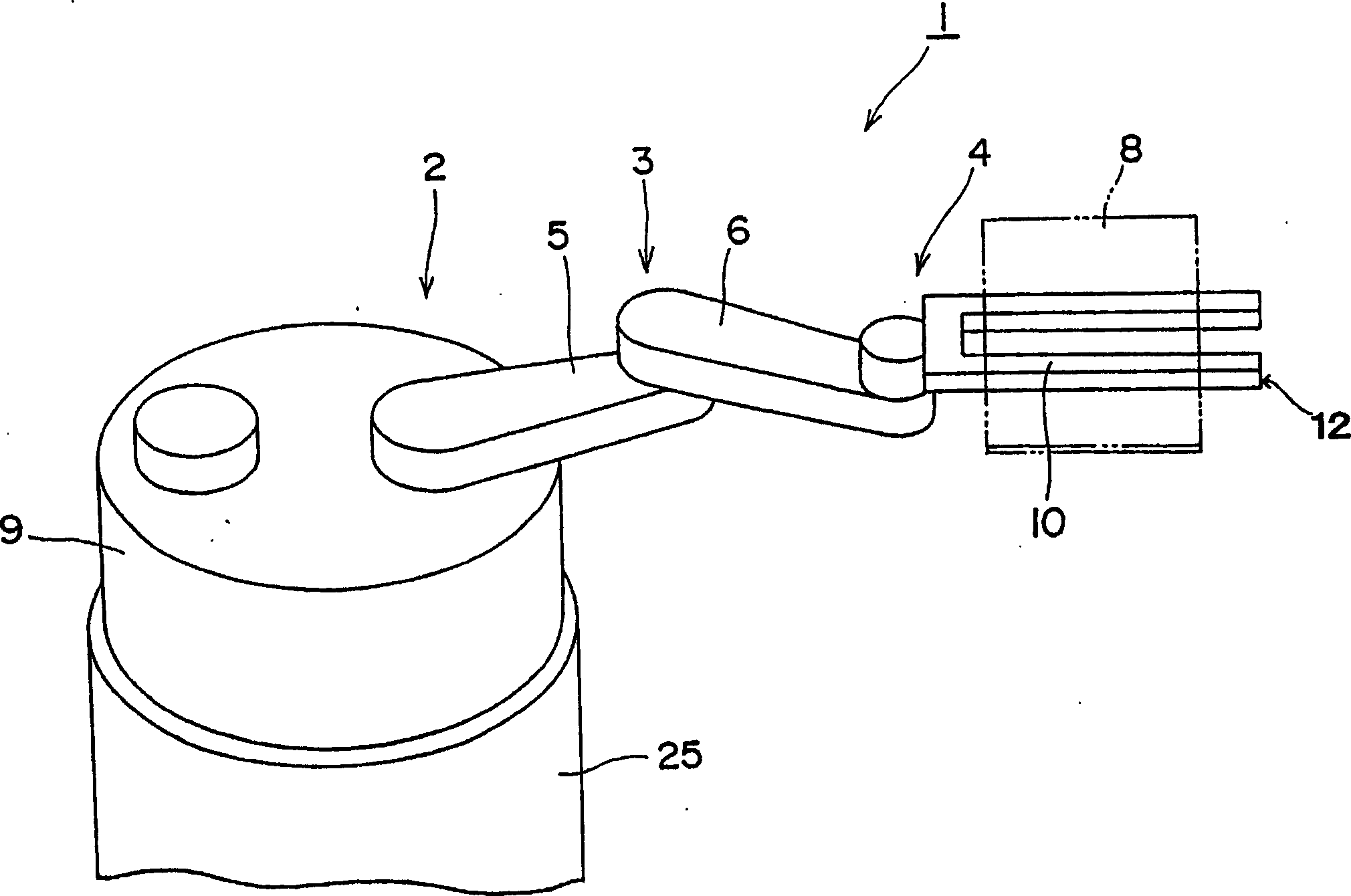
[0049] Figure 1 to Figure 5 Embodiment 1 of the industrial robot 1 of the present invention is shown. This industrial robot 1 performs operations such as assembly, processing, and transportation in the clean space 11 . Further, a particle counter for measuring the cleanliness in the clean space 11 is provided on the hand 10 of the industrial robot 1 . Therefore, the amount of particles near workpieces 8 such as semiconductor wafers and liquid crystal panels placed on the hand 10 can be measured by the particle counter, so accurate inspection can be performed.

[0050] This industrial robot 1 is, for example, an arm drive device that transports the workpiece 8 from the cassette 13 to the manufacturing device 14 . These industrial robots 1, boxes 13, and manufacturing devices 14 are all installed in a clean room 1...


PUM


Abstract

An industrial robot, the hand (2) of which is set on the side of the transport robot that takes out the transported object (3) from the storage device for storing the transported object (3) or puts the transported object (3) into the storage device The fork (4) constituting the hand (2) at the front end of the arm is made of a hollow shape, and at the same time, the thickness of the fork (4) becomes thinner toward the front end of the fork (4). The present invention can obtain high rigidity while suppressing weight.

Description

[0001] This application is a divisional application of the invention patent application with application number 200310104662.5 entitled "Industrial Robot". technical field [0002] The present invention relates to a transfer robot, and in particular to improvement of a hand of a transfer robot that moves large workpieces such as semiconductor wafers and large liquid crystals between process devices such as cassettes and coating devices. Background technique [0003] Such robots include a robot that moves semiconductor wafers or liquid crystal panels from boxes to other devices in a clean room. When handling these semiconductor wafers and liquid crystal panels, the number of particles in the clean room has a great influence on the yield, so there are several methods for inspection. [0004] For example, workers sometimes set up particle counters at defined locations in cleanrooms for periodic inspections. In addition, a particle counter may be installed in manufacturing equi...

Claims


Application Information

Patent Timeline
IPC IPC(8): B25J15/00B25J19/02B65G49/06B65G49/07H01L21/677H01L21/68
Inventor 矢泽隆之常田晴弘安川员仁吉泽丰近藤秀幸中岛弘登永泽芳水
Owner NIDEC SANKYO CORP
Why Eureka
Try Eureka