
Optical fiber polarized super fluorescent light source

A super-fluorescence and polarization technology, which is applied in the field of fiber-optic polarized super-fluorescence light sources, can solve problems such as energy loss

Inactive Publication Date: 2006-11-08
SHANGHAI INST OF OPTICS & FINE MECHANICS CHINESE ACAD OF SCI
View PDF0 Cites 5 Cited by
  • Summary
  • Abstract
  • Description
  • Claims
  • Application Information

AI Technical Summary

Problems solved by technology

Since the output of the usual super fluorescent light source is non-polarized light, in this case, 50% of the energy will be lost through a polarizer

Method used


Image

  • Optical fiber polarized super fluorescent light source
  • Optical fiber polarized super fluorescent light source

Examples


Embodiment Construction

[0018] The present invention will be further described below in conjunction with the embodiments and accompanying drawings, but the protection scope of the present invention should not be limited thereby.

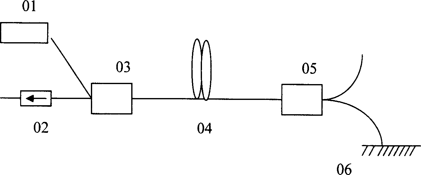
[0019] see first figure 2 , figure 2 It is a schematic structural view of the optical fiber polarized super fluorescent light source of the present invention, and is also a structural schematic view of an embodiment of the present invention. It can be seen from the figure that the optical fiber polarized super fluorescent light source of the present invention comprises: first broadband reflectors 1 are sequentially arranged on the same optical axis , the first doped fiber 2, the first dichroic plate 4, the optical isolator 5, the first polarization beam splitter 6, the Faraday rotator 7, the second polarization beam splitter 8, the second dichroic plate 10, the second doping Optical fiber 12, 1 / 4 wave plate 13, second broadband reflector 14, the angle between described f...


PUM


Abstract

This invention relates to a fiber polarized super fluorescence light source including: setting a first broadband reflector, a first doped fiber, a first double-color plate, an optical isolator, a first polarized beam-splitter, a Faraday rotatory device, a second polarized beam-splitter, a second double color plates, a second doped fiber, 1 / 4 wave plate and a second broadband reflector on a same optical axis, the included angle of the first and second double color plates and said optical axis is 45deg., a first pump light source is set at th cross point of the first double color plate and said optical axis and vertical to the optical axis, a second pump light source is set at the cross point of the second double color plate and the axis and vertical to the axis, a third broadband reflector is set at the cross point of the second polarized beam splitter and said axis and vertical to the axis direction and the direction vertical to the axis at the cross point of the first polarized beam splitter and the axis is the output direction of the polarized fluorescence light.

Description

technical field [0001] The invention belongs to an optical fiber light source, in particular to an optical fiber polarized super fluorescent light source. Background technique [0002] Hyperfluorescence is a transition state between laser and fluorescence, which is amplified spontaneous emission. Due to its superior performance such as wide bandwidth, high output power and high stability of average wavelength, doped fiber superfluorescent fiber source has been widely used in many fields such as fiber optic gyroscope, fiber optic sensing, and spectral testing. At present, most commercial broadband light sources are superluminescent diodes (hereinafter referred to as SLDs), but SLDs have short life, poor wavelength stability, low output power, and limited coupling with single-mode fibers, so doped fiber superfluorescent light sources are used as SLDs. Alternative products have great potential. [0003] In order to obtain superfluorescence in different bands, different doped ...

Claims


Application Information

Patent Timeline
IPC IPC(8): H01S3/067
Inventor 刘雁陆雨田
Owner SHANGHAI INST OF OPTICS & FINE MECHANICS CHINESE ACAD OF SCI
Learn More