Heat exchanger
A technology of heat exchangers and heat sinks, applied in the field of motor vehicle air conditioners, can solve problems such as difficult machining of heat sinks, collisions and damage of surrounding components, and achieve the effect of increasing heat transfer rate
- Summary
- Abstract
- Description
- Claims
- Application Information
AI Technical Summary
Problems solved by technology
Method used
Image
Examples
no. 1 example
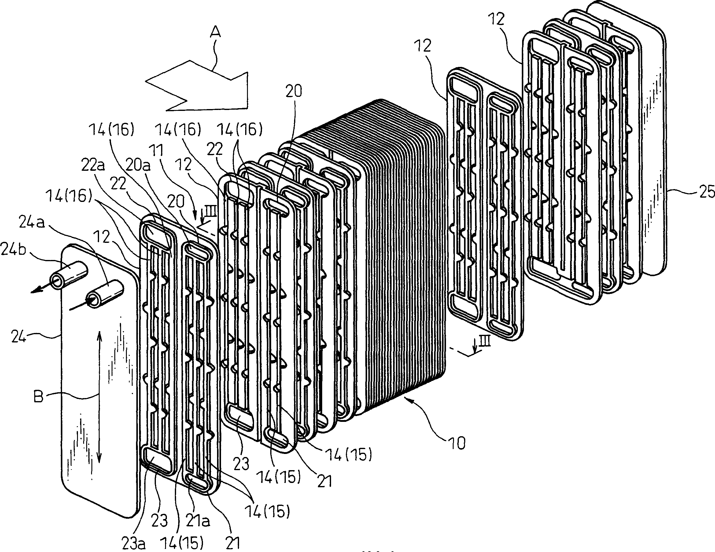
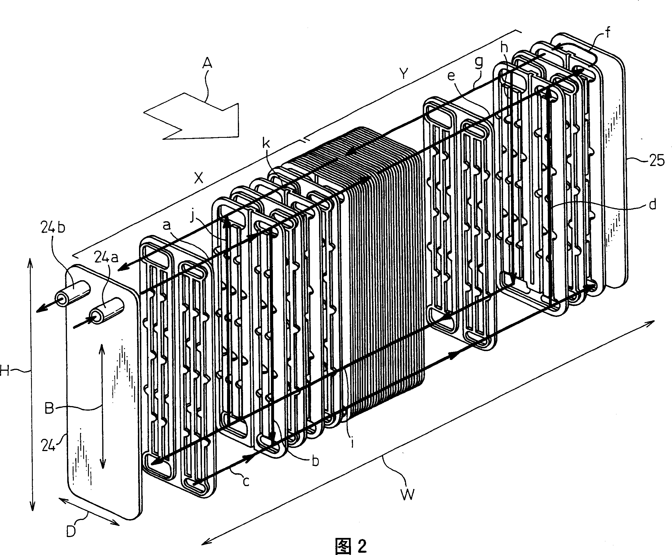
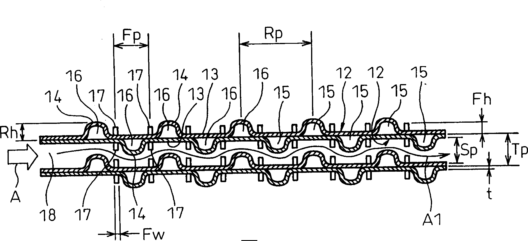
[0103] The first embodiment is an evaporator for a vehicle air conditioner. First, the overall structure of the evaporator 10 for a vehicle air conditioner will be described. figure 1 An exploded perspective view showing the outline of the general structure of the evaporator, Figure 2 is where the coolant channels indicated by arrows are added to figure 1 exploded perspective view. image 3 shows a side sectional view of the laminated structure of the heat transfer plate 12, and is along figure 1 The cross-sectional view obtained from the line I-I. Figure 4 is an enlarged perspective view of a portion of the heat transfer plate 12 .
[0104] figure 1 The general structure of the evaporator shown in and 2 is substantially the same as that disclosed in the above-mentioned first patent document (Japanese Unexamined Patent Publication No. 11-287580). The evaporator 10 is a cross-flow type heat exchanger in which the flow direction A of the air and the flow direction B of...
no. 2 example
[0187] In the first embodiment, the rib portions 14 for fixing the base plate portions 13 to each other in the two heat transfer plates 12 are provided at positions displaced from each other in the airflow direction A. As shown in FIG. In contrast, in the second embodiment, as Figure 9 As shown in , the rib portions 14 for fixing the base plate portions 13 to each other in the two heat transfer plates 12 are provided at the same position in the airflow direction A.
[0188] In the second embodiment, when the rib portions 14 having a semicircular section in the two heat transfer plates 12 are combined at the same position to form the circular coolant passages 15 and 16, the passage areas of the respective coolant passages 15 and 16 get bigger.
[0189] Thereby, it is possible to reduce the number of rib portions 14 to lengthen the mutual distance between adjacent rib portions 14 , that is, the length of the base plate portion 13 in the airflow direction. Therefore, if Figu...
no. 3 example
[0193]In the second embodiment, the rib portions 14 having a semicircular section in the two heat transfer plates 12 are combined at the same position to obtain the coolant passages 15 and 16 having a circular section. According to the third embodiment, as Figure 10A As shown in , tubular coolant passages 15 and 16 having a circular cross section are formed in a single heat transfer plate 12 by extrusion. Due to this tubular shape, rib portions 14 having a semicircular cross-section protrude from the front and rear surfaces of the single heat transfer plate 12 .
[0194] After this pressing step, the fin portions 17 are pressed out from the flat surface of the base plate portion 13 between adjacent fin portions 14 . exist Figure 10A In the embodiment shown in , the fin portion 17 is formed as a U-shaped slotted fin.
[0195] According to the third embodiment, when the tubular coolant passages 15 and 16 are formed in a single heat transfer plate 12 by extrusion, the number...
PUM
 Abstract
Description
Claims
Application Information
 - R&D
- Intellectual Property
- Life Sciences
- Materials
- Tech Scout
- Unparalleled Data Quality
- Higher Quality Content
- 60% Fewer Hallucinations
Browse by: Latest US Patents, China's latest patents, Technical Efficacy Thesaurus, Application Domain, Technology Topic, Popular Technical Reports.
© 2025 PatSnap. All rights reserved.Legal|Privacy policy|Modern Slavery Act Transparency Statement|Sitemap|About US| Contact US: help@patsnap.com


