Cast-in-place concrete plate

A cast-in-place concrete slab and cast-in-place concrete technology, applied in the field of cast-in-place concrete slabs, can solve the problems of difficult construction, time-consuming and labor-intensive work, and high cost, and achieve the effects of light weight, convenient construction, and low construction cost

Inactive Publication Date: 2006-10-25
邱则有
View PDF3 Cites 1 Cited by
  • Summary
  • Abstract
  • Description
  • Claims
  • Application Information

AI Technical Summary

Problems solved by technology

However, whether it is a hollow tube or a box, after being applied to the floor as a lightweight permanent matrix, it can form a one-way cast-in-place concrete rib hollow floor or a two-way cast-in-place concrete ribbed floor, but it cannot form a shear key two-way Floor, although Guizhou University of Technology has applied for a utility model patent with a patent number of ZL97200102.6 and the name "Reinforced Concrete Shear Key Type Two-way Hollow Slab", which discloses a shear key type two-way hollow floor, which has a self-weight Lightweight, good mechanical performance, good seismic performance, and flexible division of building space, etc., but its construction is very difficult, time-consuming, laborious, and costly

Method used


Image

  • Cast-in-place concrete plate
  • Cast-in-place concrete plate
  • Cast-in-place concrete plate

Examples


Embodiment Construction

[0054] The present invention will be further described below in conjunction with the accompanying drawings and embodiments.

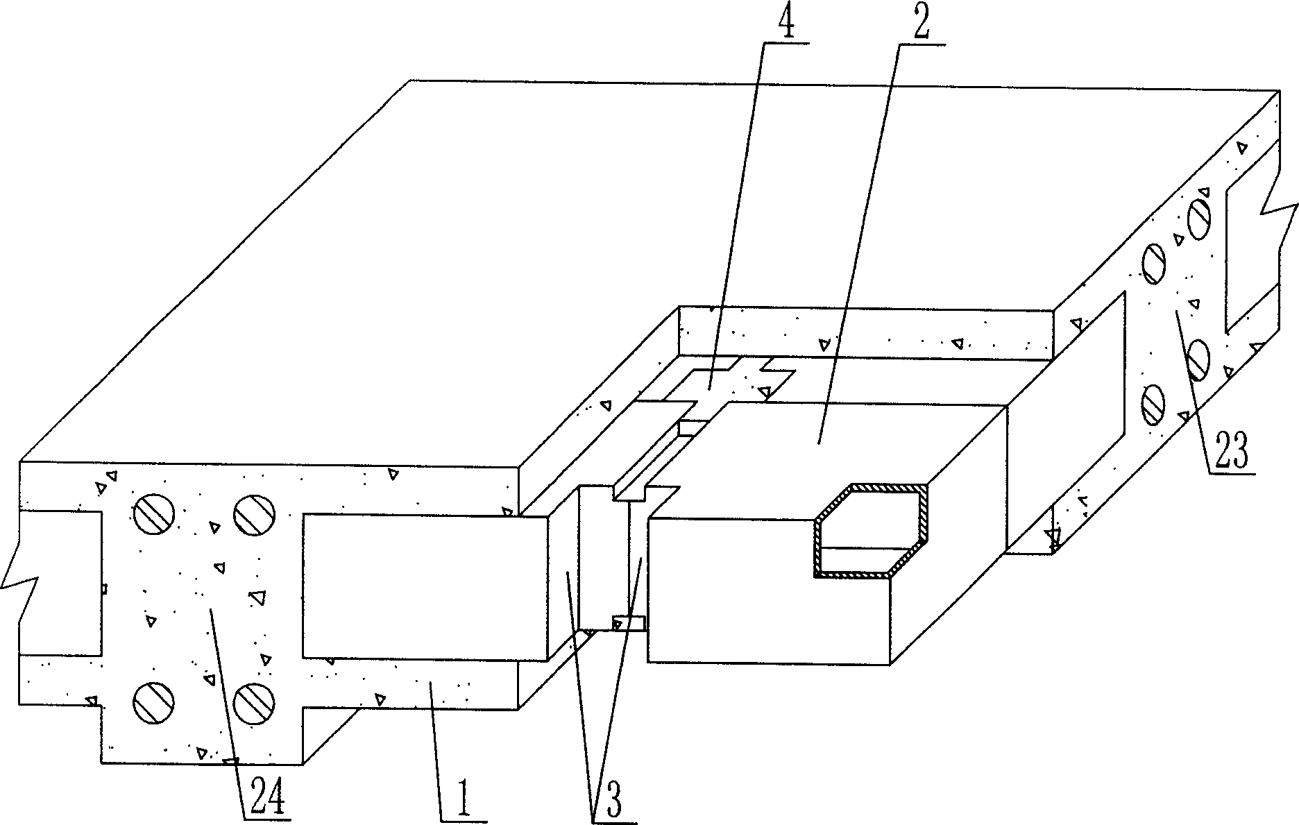
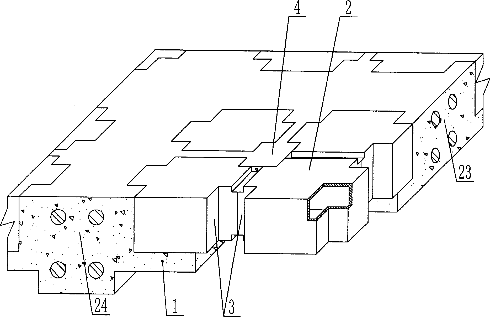
[0055] As shown in the accompanying drawings, the present invention includes reinforced concrete 1, lightweight tire mold member 2, and the lightweight tire mold member 2 is wrapped in reinforced concrete 1, and is characterized in that at least one vertical corner of the lightweight tire mold member 2 In order to penetrate the vertical inner corner 3 of the upper and lower surfaces, the lightweight tire mold members 2 are closely arranged, and the cast-in-place reinforced concrete 1 forms a cast-in-place concrete shear pier 4 at the vertical inner corner 3, and the corresponding cast-in-place concrete slab A shear pier type cast-in-place concrete slab is formed. In each drawing, 1 is reinforced concrete, 2 is lightweight tire mold member, 3 is vertical inner corner, and 4 is cast-in-situ concrete shear pier. In the following drawings, those with the sa...


PUM


Abstract

The invention is a cast-in-site concrete slab, comprising reinforced concrete, and lightweight moulding bed components, where the lightweight moulding bed components are wrapped in the reinforced concrete, and it is characterized in that at least a vertical corner of the lightweight moulding bed component is a vertical hidden angle running through top and bottom surfaces, and the lightweight moulding bed components are closely arranged, cast-in-site reinforced concrete forms cast-in-site concrete shear pier at the vertical hidden angle, and correspondingly, the cast-in-site concrete slab forms a shear pier-type cast-in-site concrete slab. And the invention is applied to cast-in-site reinforced concrete or prestressed reinforced concrete hollow floor systems, house covers, walls, foundation slabs and hollow bridges.

Description

(1) Technical field [0001] The invention relates to a cast-in-place concrete board. (2) Background technology [0002] The cast-in-place concrete slab is currently the most widely used floor structure. It has the advantages of fast construction speed, small structural height, flexible division of indoor areas and no need for ceiling decoration. The lightweight permanent tire mold filled in it has various hollow tubes. And boxes, boxes are hollow or solid. For example, the patent No. ZL99232921.3, which the applicant applied for on March 10, 1999, is a utility model patent named "thin-walled tube for filling cast-in-place reinforced concrete", which consists of a hard thin-walled tube and two plugs. It is used as a lightweight permanent tire mold in beamless slabs. Another example is Liang Jun of Shijiazhuang City, Hebei Province. The patent No. ZL00203695.9 applied for on February 23, 2000, the formwork used in the utility model patent named "combined concrete concealed ri...

Claims


Application Information

Patent Timeline
IPC IPC(8): E04B1/16E04B5/36E04C5/00E04G15/06
Inventor 邱则有
Owner 邱则有
Why Eureka
Try Eureka